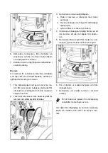
Remove the knob to slide the shift lever through
the slot in the control panel. Secure shift lever to
the shift arm with screws, washers and nuts. Re-
place the knob. Loosen the two bolts on the gear
lever for easier installation.
Discharge Chute
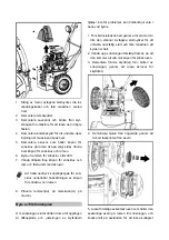
1. Grease underside of discharge chute ring (if
not already greased)
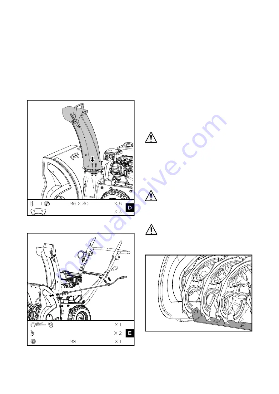
2. Install discharge chute over opening in the
auger housing and secure with fasteners.
3. Secure the upper crank lever bracket (at-
tached to the crank lever) to the upper left
side of the handlebar with a locknut and two
curved washers.
4. Apply grease to the spiral of the crank lever.
5. Insert the spiral end of the crank lever into the
lower bracket and secure with the flat washer
and clevis pin.
Tires
The tires are over-inflated at factory for shipping
purposes. Check the pressure in the tires. Re-
duce or Increase equally in both tires to the man-
ufacturer’s recommended pressure.
Under any circumstance do not exceed
manufacturer’s recommended pressure.
Excessive pressure when seating beads
may cause tire/rim assembly to burst with
force sufficient to cause serious injury.
Refer to side wall of tire for recommended
pressure.
Equal tire pressure should be maintained
at all times. If the tire pressure is not
equal in both tires, the machine may not
travel in a straight path and the shave
plate may wear unevenly.
Keep tires free of gasoline and oil, which
can harm rubber.
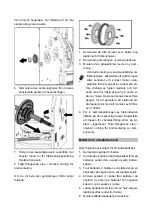
Skid Shoes
1. Move the machine to a level surface.
2. Support the auger blades so that they are
3mm (1/8”) off the ground.
3. Check the scraper blade adjustment. The
Summary of Contents for XTP120
Page 8: ......
Page 13: ......
Page 18: ......
Page 21: ......
Page 22: ......
Page 29: ......
Page 30: ......
Page 35: ......
Page 40: ......
Page 45: ......
Page 47: ......
Page 49: ......
Page 56: ......
Page 57: ......
Page 62: ......
Page 72: ......
Page 75: ......
Page 76: ......
Page 82: ......
Page 83: ......
Page 84: ......

