background image


DS-1400/1800 Installation Guide             Rev  05.12          Page 13 of 15                        Essential Trading Systems Corp. 


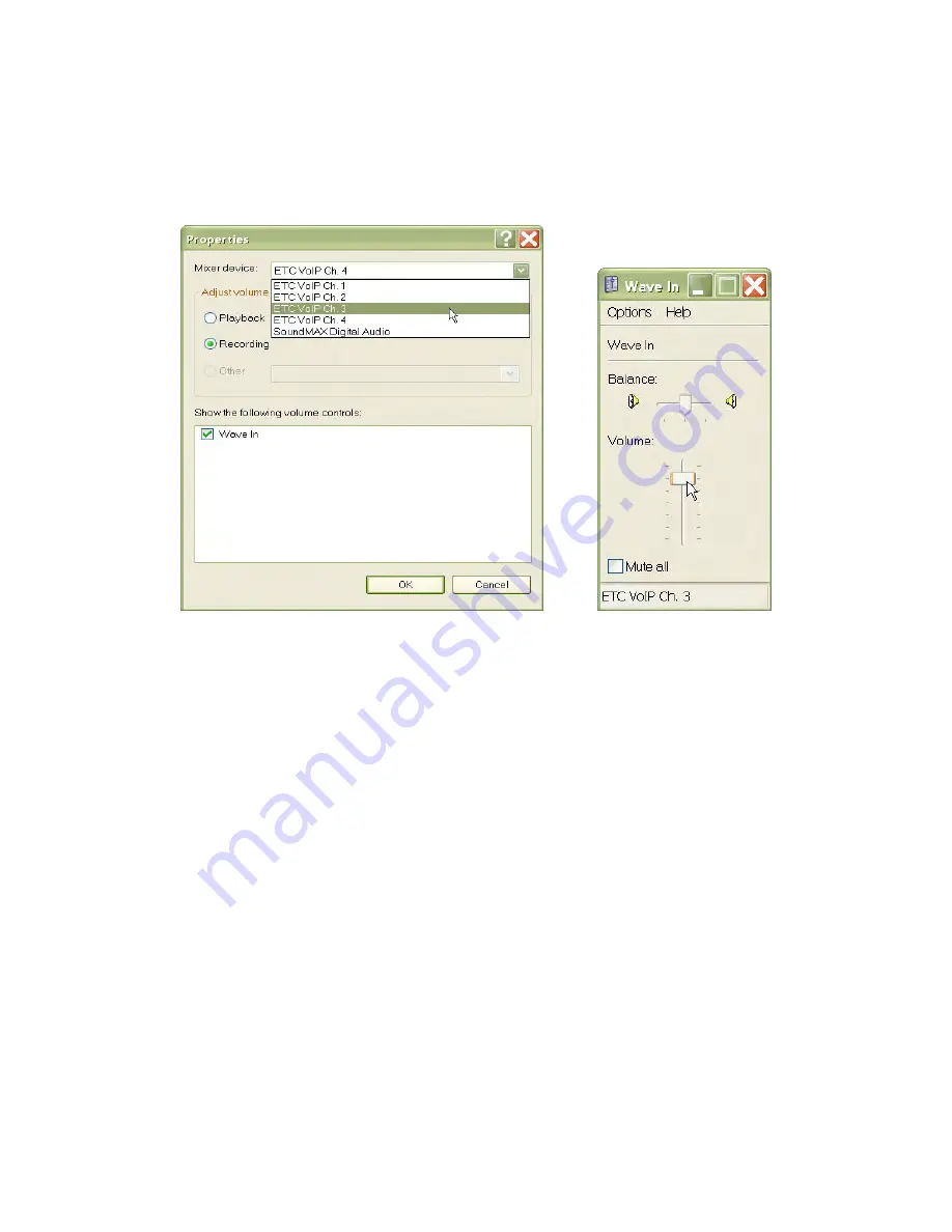
In the 

P

P

r

r

o

o

p

p

e

e

r

r

t

t

i

i

e

e

s

s window click on the 

M

M

i

i

x

x

e

e

r

r


d

d

e

e

v

v

i

i

c

c

e

e drop down menu and choose the next ETC 

channel to configure (Figure 21).   Click the 

O

O

K

K


 button


 to return to the 

W

W

a

a

v

v

e

e


I

I

n

n window, adjust 

the volume,


 and repeat the procedure for all four/eight ETC channels (Figure 22) 


    Figure 21   


            Figure 22 


After all four/eight ETC channels have been configured, close out the 

W

W

a

a

v

v

e

e


I

I

n

n window, and any 

other windows left open, and your DS-1400/1800 is ready to go.


Summary of Contents for DS-1400

Page 1: ... IE ES S A AR RE E E EN ND DL LE ES SS S 9 9 A Au us st ti in n D Dr ri iv ve e M Ma ar rl lb bo or ro ou ug gh h C CT T 0 06 64 44 47 7 8 86 60 0 2 29 95 5 8 81 10 00 0 w ww ww w e es ss se en nt ti ia al lt te el l c co om m s sa al le es s e es ss se en nt ti ia al lt te el l c co om m ...

Page 2: ...l Trading Systems Corp Table of Contents Introduction 3 Parts List 3 Physical Overview 4 Hardware Connections 6 Windows XP Audio Device Hardware Configuration 7 Specifications 14 Analog Port Pin Out 14 DS 1400 1800 Hardware Product Limited Warranty 15 Introduction ...

Page 3: ...internet in a 1 Rack Unit enclosure The DS 1400 1800 utilizes Windows application software for secure network connectivity and ETC s Viper VoIP software powered by Twisted Pair s WAVE software as transport medium Parts List DS 1400 Figure A DS 1800 Figure AA AT 1510 8C BK 10 568b patch cord Figure B HW 500 Rack screws 10 32x3 8 Figure C 18 3 gauge black PVC jacketed power cord Figure D Figure A Fi...

Page 4: ...cation of Hard Drive activity 9 PWR Provides front panel indication of the unit s on off status 10 RESET Provides front panel access to manually reset the gateway 11 POWER Power ON OFF switch Figure E Back View Figure F 12 120 VAC power connection 13 Keyboard and Mouse connection 14 VGA port connection to local monitor or KVM 15 Spare USB ports 16 NIC Ethernet and primary USB ports 17 On board sou...

Page 5: ...of requiring a switch T To o E En na ab bl le e R Rx x or having A Al lw wa ay ys s A Ac ct ti iv ve e R Rx x The E Lead option becomes critical in LMR situations where background noise can be interpreted as an analog signal Thus having Rx disabled unless the VG 400 receives a viable switch signal avoids noise Pair 3 is designated as E Lead Rx with Pin 3 as Ground and Pin 6 as logic level 3 3VDC P...

Page 6: ... to an appropriate Ethernet switch for LAN WAN connectivity The DS 1400 1800 is factory configured for DHCP but can be configured with a static IP address upon request Figure K After all external hardware components have been connected as recommended the DS 1400 1800 is ready to be powered up The device has been factory preconfigured to automatically logon with a preset username password typically...

Page 7: ... Pro operating system If you are running another Windows operating system your screens may look different Click on S So ou un nd ds s S Sp pe ee ec ch h a an nd d A Au ud di io o D De ev vi ic ce es s icon located in the C Co on nt tr ro ol l P Pa an ne el l Figure 1 Figure 1 Click on the S So ou un nd ds s a an nd d A Au ud di io o D De ev vi ic ce es s icon Figure 2 Figure 2 ...

Page 8: ...efault speaker Figure 3 This needs to be changed to ETC VoIP Ch 1 Click on the A Au ud di io o tab Figure 4 Figure 3 Figure 4 Click on the S So ou un nd d P Pl la ay yb ba ac ck k D De ef fa au ul lt t D De ev vi ic ce e drop down menu and choose ETC VoIP Ch 1 Figure 5 Click on the S So ou un nd d R Re ec co or rd di in ng g D De ef fa au ul lt t D De ev vi ic ce e drop down menu and choose ETC Vo...

Page 9: ...uture if needed Figure 8 Figure 7 Figure 8 To optimize DS 1400 1800 performance sound card settings must be adjusted after device installation Click on the A Ad dv va an nc ce ed d button in the D De ev vi ic ce e v vo ol lu um me e box Figure 9 The ETC VoIP Ch 1 S Sp pe ea ak ke er r mixer window will open If your window does NOT show a M Mi ic cr ro op ph ho on ne e device you will need to activ...

Page 10: ...ll see a M Mi ic cr ro op ph ho on ne e device for ETC VoIP Ch 1 in the S Sp pe ea ak ke er r window Using your cursor move the S Sp pe ea ak ke er r master volume lever up to the recommended playback level shown Figure 12 Figure 11 Figure 12 The M Mi ic cr ro op ph ho on ne e volume lever must be down all the way and the M Mu ut te e b bo ox x m mu us st t b be e c ch he ec ck ke ed d F Fi ig gu ...

Page 11: ... will cause echo on the network and down time for troubleshooting your installation From the O Op pt ti io on ns s drop down menu choose P Pr ro op pe er rt ti ie es s Figure 14 In the P Pr ro op pe er rt ti ie es s window click on the M Mi ix xe er r d de ev vi ic ce e drop down menu and choose the next ETC channel to configure Figure 15 Figure 14 Figure 15 ...

Page 12: ... devices can now be adjusted From the O Op pt ti io on ns s drop down menu choose P Pr ro op pe er rt ti ie es s Figure 17 Figure 16 Figure 17 In the P Pr ro op pe er rt ti ie es s window click on the R Re ec co or rd di in ng g circle and click the O OK K button Figure 18 The W Wa av ve e I In n recording level window will appear Adjust the volume to the recommended level Figure 19 From the O Op ...

Page 13: ...u and choose the next ETC channel to configure Figure 21 Click the O OK K button to return to the W Wa av ve e I In n window adjust the volume and repeat the procedure for all four eight ETC channels Figure 22 Figure 21 Figure 22 After all four eight ETC channels have been configured close out the W Wa av ve e I In n window and any other windows left open and your DS 1400 1800 is ready to go ...

Page 14: ...g System Embedded XP Pro Power 120 VAC 95 Watts Dimensions H 1 75 x W 19 x D 14 5 1 Rack Unit Environmental Requirements 5 35 C 50 95 F operating temp 10 90 non condensing relative humidity Analog Port Pin Out Each analog output is an RJ 45 conforming to EIA TIA 568b standards The pin out is as follows in reference to the device s analog port Pair Pin Color Description 1 4 Blu Wht Receive Tip RxT ...

Page 15: ... however this period of time may vary depending on where you purchased your product please check with ETC for details Warranty claims or other product related questions should be addressed directly to ETC The addresses and customer service contact information for ETC can be found in the documentation accompanying your product and on the web at www essentialtel com ETC SHALL NOT BE LIABLE FOR ANY S...

Reviews: