DS-1400/1800 Installation Guide Rev 05.12 Page 5 of 15 Essential Trading Systems Corp.
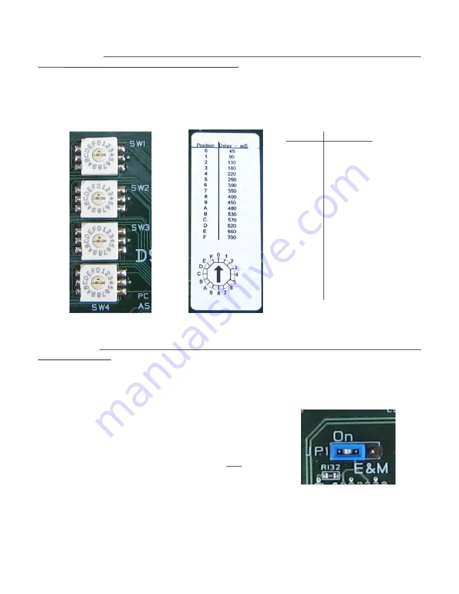
“M” Lead (Tx): Both the VG-1400 and VG-1800 have the “M” Lead option of adjustable time-
delay
P
P
u
u
s
s
h
h
T
T
o
o
T
T
r
r
a
a
n
n
s
s
m
m
i
i
t
t
(
(
P
P
T
T
T
T
)
)
c
c
o
o
n
n
t
t
a
a
c
c
t
t
c
c
l
l
o
o
s
s
u
u
r
r
e
e. The “M” Lead option becomes critical in
matching transmit delay to equipment key-up time. Each of the four channels has a dedicated
16 position adjusting switch (Figure H). Included on the back of the board is a label (Figure I)
showing the switch adjustment position to time delay correlation (Figure J). The PTT Dry
Contact is a solid state non-polarized Normally Open (NO) relay. Specification maximum values
are 100VDC max. Open; 150mA current and 8
Ω
max resistance Closed.
Figure G Figure H
Figure I
“E” Lead (Rx): Only the VG-1400 has the option of requiring a switch
T
T
o
o
E
E
n
n
a
a
b
b
l
l
e
e
R
R
x
x
or having
A
A
l
l
w
w
a
a
y
y
s
s
A
A
c
c
t
t
i
i
v
v
e
e
R
R
x
x
.
.
The “E” Lead option becomes critical in LMR situations where background
noise can be interpreted as an analog signal. Thus, having Rx disabled unless the VG-400
receives a viable switch signal avoids noise. Pair 3 is designated as “E” Lead Rx with Pin 3 as
Ground and Pin 6 as logic level +3.3VDC. Pulling or “Pinning Up” Pin 3 to Pin 6 is what enables
Rx to activate. The DS-1400 uses jumper JP1 (Figure J) to globally enable or disable this
feature.
•
By positioning JP1 in “E & M” mode, the board
requires a switch signal
T
T
o
o
E
E
n
n
a
a
b
b
l
l
e
e
R
R
x
x.
•
By positioning JP1 in “On” mode, which is the factory
default setting (Figure J), the board does not require a
switch signal and is
A
A
l
l
w
w
a
a
y
y
s
s
A
A
c
c
t
t
i
i
v
v
e
e
R
R
x
x
.
.
Figure J
To access these settings, remove the top cover of the DS-1400/1800.
Position Delay - mS
0 45
1 90
2 130
3 180
4 220
5 260
6 300
7 350
8 400
9 450
A 480
B 530
C 570
D 620
E 660
F 700


