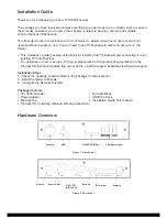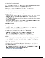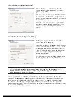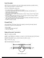
I/O Terminal (RS485/422/Alarm/DC): Provides RS485/422 data connections, an alarm input
connection and an additional DC power input.
Figure 4: I/O Terminal
The RS485/422 connectors can be used to drive PTZ cameras or operate camera relays. The cable
for connecting PTZ cameras will depend on the make and model of camera. Consult the camera
documentation and the table below to produce a suitable cable.
NOTE:
• Depending on manufacturer interpretation of RS485/422 standards the Transmit and Receive lines
may have the polarity reversed.
• The Network Encoder can be powered via the 12V DC Power Input jack or through screw terminal
pins 9 and 10.
Do not use both power inputs simultaneously.
Further Information
Information on using the Encoder and viewing video streams can be found on the Product CD that
accompanies this unit or online via
http://support.essential-viewing.com/support.
1
2
3
4
5
6
7
8
9
10
RS485 /422
Alarm
Input
Power
Input
PIN
Description
Specification
1 (leftmost)
RS485/422 GND
2
RS485/422 Trans (or B)
3
RS485/422 Transmitted – (or A)
4
RS485/422 GND (optional)
5
RS422 Re
6
RS422 Received -
7
Alarm Trigger Input
Off: 0V – 2.5V DC
On: 4.5V – 36V DC
8
Isolated GND for Alarm Input Trigger
9
Power Input
0V – 36V DC
10 (rightmost)
Power GND


