connecting to the gas cylinder
connecting to the gas cylinder
V.1.0
V.1.0
34
35
Connecting the hose and regulator (not supplied)
This appliance is designed to be used in accordance with the information given in the tables below:
Country of destination
Category
Gas and pressure
FRANCE, BELGIUM,
LUXEMBOURG
I
3+
(28-30/37 mbar)
G30 - Butane: 28-30 mbar
G31 - Propane: 37 mbar
Rated power (∑Qn)
7.05kW (513.2g/h on Butane – 504.1g/h on Propane)
Mark on injector
0.75
•
The G1/2 gas inlet is located on the left side of the appliance.
•
Use a hose that complies with the national regulations in force (NF for France, BSEN 16129:2013
for other countries) of 37 mbar for Propane or 28-30 mbar for Butane with G1/2 threaded nut for
screwing into the appliance, and M20×1.5 threaded nut on the regulator, complying with NF D 36-
125 or XP D 36-112.
•
Comment:
for other countries, cylinders and regulators must comply with applicable national regulations.)
•
The connection to the appliance must be made using a 1.2 m or 1.5 m long supply hose (maximum).
•
Change the main supply hose before its expiry date, if it is damaged, if it shows cracks, or when
national legislation requires it.
•
Do not pull or twist the hose.
•
Make sure that the hose is not subjected to torsional or tensile stress: the gas inlet connector is
located on the left side and the gas cylinder is positioned on the left side of the appliance.
•
Make sure that the hose is never in contact with parts of the appliance that may become hot.
Warning!
Never connect your appliance to town gas (natural gas). The gas circuit is
designed exclusively for butane/propane gas (G30/G31).
!
CONNECTOR:
FOR FRANCE
Use the G1/2 gas inlet located on the left side or rear side of the barbecue.
FOR OTHER COUNTRIES
Use the ringed connector supplied as a spare part.
Firmly screw the ringed connector onto the G1/2 gas inlet threaded connector using a suitable
tightening tool (wrench) and carry out the leak test (see next paragraph).
SUPPLY HOSE: FOR ALL COUNTRIES
Change the main supply hose before its expiry date, if it is damaged, if it shows cracks, or when
national legislation requires it. The hose must comply with EN16436-1:2014.
Do not pull or twist the hose.
Make sure that the hose is not subjected to torsional or tensile stress: the gas inlet connector is located
on the left side and the gas cylinder is positioned on the left side of the appliance.
Make sure that the hose is never in contact with parts of the appliance that may become hot.
Place the gas cylinder at least 1 metre away from the barbecue.
The connection to the appliance must be made using a 1.2 m or 1.5 m long supply hose (maximum).
Leak test
1.
Make sure that all of the control knobs are in the closed position “
•
” (stop).
2.
Prepare a soap and water solution (1/2 water and 1/2 soap) and run the solution through the gas
connection points of the cylinder, regulator, hose and gas connection using a brush.
3.
Open the gas cylinder valve.
Warning!
•
This test must be carried out in a well-ventilated area before using the griddle, every
year, after a long period of disuse, or when replacing the gas cylinder.
•
Do not check for gas leaks near an open flame. If you smell gas, immediately turn off
the gas supply.
!
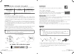
Soap
To regulator
To griddle
(Non-contractual diagrams)
Fig. 1: Tightening by hand is sufficient. Do not overtighten
V.1.0
raccordement à la bouteille de gaz
15
Branchement du tuyau et du détendeur (non fournis)
Cet appareil est conçu pour être utilisé en conformité avec les informations indiquées dans les tableaux
ci-dessous :
Pays de destination
Catégorie
Gaz et pression
FRANCE
I
3
(28-30/37 mbar)
G30 - Butane : 28-30 mbar
G31 - Propane : 37 mbar
Puissance nominale (∑Qn)
7.0 kW (509 g/h au butane, 500 g/h au propane)
Repère sur injecteur
106
•
L’entrée gaz G1/2 se situe sur le côté latéral gauche de l'appareil.
•
Utilisez un tuyau conforme à la réglementation nationale en vigueur (NF) avec écrou fileté G1/2 pour
le vissage sur l’appareil, et écrou fileté M20×1.5 sur le détendeur, conforme à la norme NF D 36-125
ou à la norme XP D 36-112.
•
Le raccordement à l’appareil doit se faire à l’aide d’un tuyau d’alimentation de longueur 1,2 m ou
1,5 m maximum.
•
Changez le tuyau principal d’alimentation avant sa date de péremption, s’il est endommagé, s’il
présente des craquelures, ou lorsque les conditions nationales l’exigent.
•
Ne tirez pas sur le tuyau ou ne le vrillez pas.
•
Veillez à ce que le tuyau ne soit pas soumis à des efforts de torsion ou traction : l’embout de
raccordement d’entrée gaz se situant sur le côté latéral gauche, positionnez le récipient de gaz à
gauche de l’appareil.
•
Veillez à ce que le tuyau ne soit jamais en contact des parties de l’appareil susceptibles de devenir
chaudes.
Attention !
Ne raccordez jamais votre appareil au gaz de ville (gaz naturel). Le circuit de
gaz est conçu exclusivement pour le gaz butane/propane (G30/G31).
!
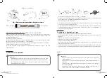
Fig. 1
Fig. 3
Fig. 2
Vers détendeur
Vers plancha
1.
Utilisez un tuyau comportant un marquage NF et écrou fileté G1/2 pour le vissage sur l’appareil, et
écrou fileté 20×1.5 sur le détendeur, conforme à la norme XP D 36-125 ou à la norme XP D 36-112.
2.
Vérifiez que toutes les manettes de commande de la plancha sont sur la position «
•
» (arrêt).
3.
Vissez l’écrou fileté G1/2 du tuyau sur le raccord d’entrée de l’appareil (figure 1 ci-dessus) et
l’écrou fileté M20×1.5 (de couleur noire) sur le raccord de sortie du détendeur (figure 2 ci-dessus)
en suivant les indications fournies avec le tuyau souple.
4.
Vérifiez l’étanchéité de l’ensemble en effectuant un test de fuite (voir section suivante « Test de
fuite »).
5.
Branchez le détendeur sur la bouteille de gaz (figure 3 ci-dessus). Reportez-vous aux instructions
relatives à l'installation du détendeur et de la bouteille.
(Schémas non contractuels)


