background image

13

Essex Electronics, Inc. | 805.684.7601 | 800.KEY-LESS | fax 805.684.0232 | keyless.com

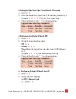
 Setting the Main Door Open Time (Default: 5 Seconds)

a.  Enter  

2    #

b.  Enter the desired Door Open Time (1-99 seconds), followed by  

#


Example:  

2    #    1    5    #

  (15 sec. Door Open Time)

c.  Return to Step 3 or enter 


*


*

  to exit programming.

Keypad Status After Step Completion

Step 

Beep  Red LED 

Green LED

Double  Fast Flash  Slow Flash

Triple  Fast Flash  Solid


 Setting Latching Option (Default: Off)

a.  Enter  

3    #

b.  Select the desired latching option:


Off-  

0    #


Manual-  

9    9    #


Timed- Enter the desired time interval in hours (1-98), followed  


by  

#


Example:  

3   #    8   #

  (Sets timed latching for 8 hrs)

c.  Return to Step 3 or enter  

*


*

  to exit programming.

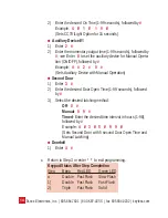
Keypad Status After Step Completion

Step 

Beep  Red LED 

Green LED

a Double 

Fast Flash  Slow Flash

b Triple 

Fast Flash Solid

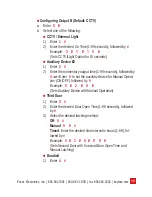
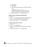
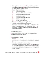
   Configuring Output A (Default: Aux #1)

a.  Enter  

4    #

b.  Select one of the following:

 CCTV / External Light

1)  Enter  

1    #

Summary of Contents for SKE-26B

Page 1: ...Essex Electronics Inc 805 684 7601 800 KEY LESS fax 805 684 0232 keyless com Installation Instruction Manual SKE Series 12 Pad ...

Page 2: ...ument Information IOMK1 Installation Operations Manual for the SKE Series 12 Pad 3x4 and 2x6 December 2014 This documentation is also appli cable to prior revisions except where noted Trademarks Keyless Entry is a registered trademark of Essex Electronics Inc Certifications The SKE 34 is listed by CSA for Elevator Equipment CSA B44 1 04 ASME A17 5 2004 Class 2411 02 Contact Information Essex Elect...

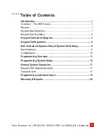
Page 3: ...1 Keypad Part Numbers 2 Keypad Connector Diagram 3 Keypad Configuration 5 Self Contained Keyless Entry System With Relay 9 Specifications 9 Configuration 10 Programming Overview 11 Programming System Setup 12 Normal System Operation 17 Keypad LED Status Indicators 17 Tamper Alarm 17 Programming Individual Users 18 Warranty Repairs 24 Table of Contents ...

Page 4: ...Essex Electronics Inc 805 684 7601 800 KEY LESS fax 805 684 0232 keyless com iii ...

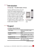
Page 5: ... lock either fail safe or fail secure It can also trigger a contact closure to activate an automatic door opener or gate operator There are two additional open collector outputs With 2 installer provided external relays up to 3 devices can be controlled Input Voltage 5VDC or 12 to 24VDC Jumper Selectable Standby Current Draw 25mA Outputs 1 Relay 24VAC DC Max 2A Max 2 Open Collector 1 4 A Max to Gr...

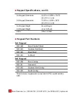
Page 6: ...d SKE 26B Brass Overlay SKE 26I Illuminated SKE 26S Stainless Steel Overlay SKE 26R Braille Overlay Bezel is brass in appearance Actual bezel is PVD coated stainless steel 3x4 Keypad Dimensions 5 1 8 H x 3 3 8 W x 7 16 D 13 x 8 6 x 1 1 cm 2x6 Keypad Dimensions 7 1 8 H x 1 3 4 W x 3 4 D 13 x 8 6 x 1 1 cm 3x4 Keypad Weight 16 oz 454 gm 2x6 Keypad Weight 4 4 oz 125 gm LED s 1 Red 1 Green Keypad Speci...

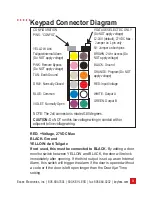
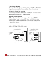
Page 7: ... door is left open longer than the Door Ajar Time setting CONFIGURATION PINS CONFIG VOLTAGE SELECT DC ONLY Do NOT apply voltage 12 24V default 27VDC Max Jumper on 1 pin only 5V Jumper on both pins YELLOW Anti Tailgate Internal Alarm Do NOT apply voltage PINK Remote Bypass Do NOT apply voltage BLUE Common BROWN 24 hr Access Do NOT apply voltage TAN Earth Ground BLACK Ground ORANGE Program Do NOT ap...

Page 8: ... Code BROWN 24 hour Access If Time Clock is enabled in Set up page 16 and the BROWN wire is grounded all codes work normally When the BROWN wire is not grounded only those codes with 24 hour Access Authorization page 17 will function Internal Relay Wiring Diagram 12 24VDC Power Supply RED BLACK YELLOW BLUE VIOLET GRAY FAIL SECURE FAIL SAFE MOV K E Y P A D 12 24VDC Power Supply VIOLET YELLOW BLACK ...

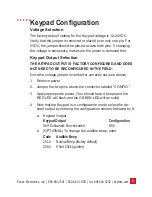
Page 9: ...ry configured and does not need to be reconfigured in the field Once the voltage jumper is verified or correctly set see above 1 Remove power 2 Jumper the two pins above the connector labeled CONFIG 3 Apply appropriate power You should hear 4 beeps and the RED LED will flash and the GREEN LED will be solid 4 Now that the Keypad is in configuration mode select the de sired output by entering the co...

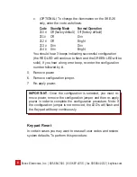
Page 10: ...e to flash and the GREEN LED will be solid If you hear a long error beep re enter the configuration number followed by 5 Remove power 6 Remove configuration jumper 7 Re apply power IMPORTANT Once the configuration is selected you must re move power remove the configuration jumper and then re apply power in order to complete the configuration procedure Note If the configuration jumper is not remove...

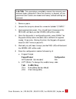
Page 11: ...s and the RED LED will flash and the GREEN LED will be solid 4 Once the Keypad is in configuration mode enter 0099 The Keypad will beep twice and both LEDs will flash for approxi mately 10 seconds During this time the Keypad will appear dead Do NOT remove power 5 Wait and you will hear 4 beeps and the RED LED will flash and the GREEN LED will be solid 6 Enter the configuration number followed by a...

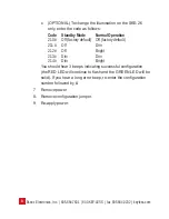
Page 12: ... Normal Operation 210 Off factory default Off factory default 211 Off Dim 212 Off Bright 213 Dim Dim 214 Dim Bright You should hear 3 beeps indicating successful configuration the RED LED will continue to flash and the GREEN LED will be solid If you hear a long error beep re enter the configuration number followed by 7 Remove power 8 Remove configuration jumper 9 Re apply power ...

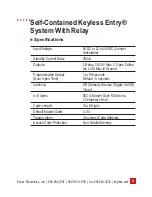
Page 13: ...Standby Current Draw 25mA Outputs 1 Relay 2A 24V Max 2 Open Collec tor 1 4 A Max to Ground Programmable Output 1 to 99 seconds Door Open Time Default 5 seconds Latching Off Default Manual Toggle On Off Timed of Users 502 1 Master User 500 Users 1 Temporary User Code Length 3 to 8 Digits Default Master Code 1 2 3 Tamper Alarm 4 Incorrect Code Attempts Access Code Protection Non Volatile Memory ...

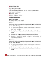
Page 14: ... for one of the following 1 CCTV or Light Controller First key press triggers a Timed Out put 1 to 99 seconds 2 Auxiliary Output Manual Control or Timed Output 1 to 99 sec onds 3 Second Door Users can be assigned to open a 2nd door 4 Doorbell Press at the Keypad to trigger a 1 second output for a doorbell not included Output B A transistor output intended to drive a relay that can be programmed fo...

Page 15: ...Code setting the main relay opening time allows latching toggling of the main relay etc 1 is the Programming Command for programming user codes page 18 When programming the user codes you have the ability to assign users authorizations You can authorize a user to latch if the system was set up to latch in the 3 programming sequence you can allow a user to program or delete codes or activate one of...

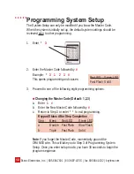
Page 16: ... and causes 3 Proceed to one of the following eight programming options Changing the Master Code Default 1 2 3 a Enter 1 b Enter the New Master Code followed by c Return to Step 3 or enter to exit programming Keypad Status After Step Completion Step Beep Red LED Green LED a Double Fast Flash Slow Flash b Triple Fast Flash Solid Note If you forget the Master Code momentarily ground the ORANGE wire ...

Page 17: ...en LED a Double Fast Flash Slow Flash b Triple Fast Flash Solid Setting Latching Option Default Off a Enter 3 b Select the desired latching option Off 0 Manual 9 9 Timed Enter the desired time interval in hours 1 98 followed by Example 3 8 Sets timed latching for 8 hrs c Return to Step 3 or enter to exit programming Keypad Status After Step Completion Step Beep Red LED Green LED a Double Fast Flas...

Page 18: ...ample 4 2 0 Sets Auxiliary Device with Manual Operation Second Door 1 Enter 3 2 Enter the desired Door Open Time 1 99 seconds followed by 3 Select the desired latching method Off 0 Manual 9 9 Timed Enter the desired time interval in hours 1 98 followed by Example 4 3 5 9 9 Sets Second Door with 5 second Door Open Time and Manual Latching Doorbell 1 Enter 4 c Return to Step 3 or enter to exit progr...

Page 19: ... 1 Enter 2 2 Enter the momentary output time 1 99 seconds followed by or Enter 0 to set the auxiliary device for Manual Opera tion ON OFF followed by Example 5 2 0 Sets Auxiliary Device with Manual Operation Third Door 1 Enter 3 2 Enter the desired Door Open Time 1 99 seconds followed by 3 Select the desired latching method Off 0 Manual 9 9 Timed Enter the desired time interval in hours 1 98 fol l...

Page 20: ...hen triggered c Return to Step 3 or enter to exit programming Master Code Door Unlock Option Default Allow a Enter 6 b Enter 0 to prevent the master code from unlocking the door c Enter 1 to allow the master code to unlock the door d Return to Step 3 or enter to exit programming Time Clock Input Default Prevent a Enter 7 b Enter 0 to prevent lockout c Enter 1 to lockout all users that do not have ...

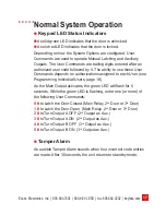
Page 21: ...hese User Commands depends on authorizations assigned to each User see Programming Individual Users page 18 As the Main Output activates the green LED will flash for 5 seconds While the green LED is flashing enter one or more of the following User Commands 0 to Latch the Door Closed Main Relay 2nd Door or 3rd Door 1 to Latch the Door Open Main Relay 2nd Door or 3rd Door 2 to Turn Output A OFF 2nd ...

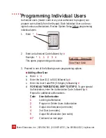
Page 22: ...his opens programming and causes 3 Proceed to one of the following seven programming options Adding a New User a Enter 1 b Enter the User ID 1 to 500 followed by c Enter the User Code PIN 3 8 digits followed by d FOR NO AUTHORIZATIONS SKIP TO STEP E To give special Authorizations enter the Authorization Code followed by Repeat for additional authorizations Code User Authorization 1 Latching Author...

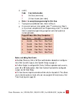
Page 23: ...etion Step Beep Red LED Green LED a Double Slow Flash Slow Flash b Double Slow Flash Fast Flash c Double Slow Flash Fast Flash d Double Slow Flash Fast Flash e Triple Slow Flash Slow Flash Notes on Adding New Users Auxiliary Device or 2nd or 3rd Door authorization depends on configura tion of the A and B Outputs See System Setup on page 12 If either Output is configured for 2nd or 3rd Door operati...

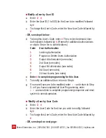
Page 24: ...ization 2 Program or Delete Users Authorization 3 Output AAuthorization see notes 4 2nd Door see notes 5 Output B Authorization see notes 6 3rd Door see notes 7 24 hour Access see notes e Enter to complete programming for this User f To modify an additional User return to Step b g If no more Users are to be modified enter and return to Step 3 or if you have completed all User Programming enter a s...

Page 25: ... modify an additional User return to Step b g If no more Users are to be modified enter and return to Step 3 or if you have completed all User Programming enter a second time to complete programming sequence and reset sys tem to normal operation Note on Modifying Users Once you have begun to modify a User previously programmed authorizations are deleted for this User Deleting a User by User ID a E...

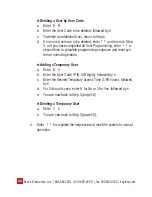
Page 26: ... all User Programming enter a second time to complete programming sequence and reset sys tem to normal operation Adding a Temporary User a Enter 6 b Enter the User Code PIN 3 8 digits followed by c Enter the desired Temporary access Time 1 99 hours followed by d For 24 hour Access enter 0 for No or 1 for Yes followed by e You are now back to Step 3 page 18 Deleting a Temporary User a Enter 7 b You...

Page 27: ...23 Essex Electronics Inc 805 684 7601 800 KEY LESS fax 805 684 0232 keyless com Notes ...

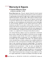
Page 28: ... substitute product may be provided at Essex s election as a replacement for the original discontinued product This Limited Warranty extends only to the original retail or wholesale Buyer and the original site of installation It does not cover any damage to this product or parts thereof if the product is installed in violation of the applicable codes or ordinances or is not installed and used in a...

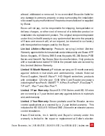
Page 29: ... Series SKE Series Keypads KE 265 Series PEB Series and Hand E Tap Series Door Access Switches Only products with a manufactured date of 5 1 06 to the present date are covered by this Limited Lifetime Warranty Limited 18 Month Warranty Products carrying an 18 month warranty against defects in materials and workmanship include External Power Supplies Hand E Wave HID Edge controllers products with e...

Page 30: ...Essex Electronics Inc extends no warranty of any kind express or implied and disclaims any implied warranty of merchantability or suitability for purpose for which sold with respect to the keypads keyless entry coded access system or accessories Except for the limited repair or replacement specified above under no circumstances will Essex Electronics Inc be liable to buyer under or in connection w...

Page 31: ...ty California Repair Policy Should it be necessary for a component or a system to be returned for repair it must be accompanied with an RA Return Authorization Number issued by the factory Please call 1 800 KEYLESS 800 539 5377 to obtain an RA All returns must be sent to the factory freight prepaid Collect shipments will not be accepted at any time Standard turnaround time is ten 10 working days f...

Page 32: ...Essex Electronics Inc 805 684 7601 800 KEY LESS fax 805 684 0232 keyless com ...

Reviews: