Caution: Disconnect all electrical power at the breaker or fuse box before you begin to install, service or open your cooler
Warning: to reduce the risk of fire or electrical shock, DO NOT use this fan with any solid-state speed control device.
Electrical Connections
1. All wiring must conform to local codes.
2. If this unit is to be controlled by a remote switch, use an Essick 6-position switch (ECR-6) or an equivalent UL switch
with an electrical rating of
120 Volt, 25 Amp and 1 ¼ HP maximum
.
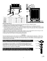
3. The junction box is mounted in the corner of the unit. A knock-out is
provided for connecting electrical conduit.
4. All wiring connections must be made inside the junction box. See wiring
diagram below.
Note: If you have a one speed motor, the low speed settings of your switch
will not be operative.
Motor Installation and Adjustment: (IMPORTANT INFORMATION)
Complete the following before you fill the cooler pan with water.
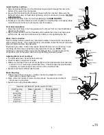
1. Install the motor pulley with the threaded side out.
2. Tighten the set screw opposite the threaded side onto the flat of the shaft.
3. Loosen the set screw on the threaded side of the pulley until that jaw rotates freely.
4. Turn the jaw clockwise until pulley is fully closed, then turn the jaw counterclockwise until the set screw is over the
closest flat spot. This is the fully closed position.
closest flat spot. This is the fully closed position.
5. From the fully closed position open the pulley 3 full turns and tighten the set screw.
DO NOT tighten the set screw
onto the threads. This will damage the pulley.
5. From the fully closed position open the pulley 3 full turns and tighten the set screw.
DO NOT tighten the set screw
onto the threads. This will damage the pulley.
6. Find the amperage on the motor nameplate.
6. Find the amperage on the motor nameplate.
7. Install the louvers and ensure exhaust openings in the structure (usually windows) are open to the required position.
7. Install the louvers and ensure exhaust openings in the structure (usually windows) are open to the required position.
8. Start the cooler on high vent (no pump).
8. Start the cooler on high vent (no pump).
9. Using a clamp-type ammeter, check the motor amperage by clamping the ammeter around the incoming white lead.
9. Using a clamp-type ammeter, check the motor amperage by clamping the ammeter around the incoming white lead.
10. If amperage is less than motor nameplate amps, remove the belt, loosen the adjustment set screw and close the
pulley one full turn. Tighten the adjustment set screw, replace the belt and check amperage again. Repeat as
necessary until amperage reads just under motor nameplate.
10. If amperage is less than motor nameplate amps, remove the belt, loosen the adjustment set screw and close the
pulley one full turn. Tighten the adjustment set screw, replace the belt and check amperage again. Repeat as
necessary until amperage reads just under motor nameplate.
11. If amperage is too high, remove the belt, loosen the adjustment set screw and open the pulley one full turn. Tighten
the adjustment set screw, replace the belt and check amperage again. Repeat as necessary until amperage reads just
under motor nameplate.
11. If amperage is too high, remove the belt, loosen the adjustment set screw and open the pulley one full turn. Tighten
the adjustment set screw, replace the belt and check amperage again. Repeat as necessary until amperage reads just
under motor nameplate.
12. When amperage reads correctly, adjust belt tension as necessary and recheck belt alignment.
12. When amperage reads correctly, adjust belt tension as necessary and recheck belt alignment.
Start Up
Start Up
Before starting your cooler for the first time, check the following.
Before starting your cooler for the first time, check the following.
Cooler is grounded and all electrical connections are
safe and secure.
Cooler is grounded and all electrical connections are
safe and secure.
Cooler is level and duct is sealed.
Cooler is level and duct is sealed.
Blower wheel does not rub housing.
Blower wheel does not rub housing.
Water supply is turned on.
Water supply is turned on.
Drain fitting and water connections are secure and do
not leak.
Drain fitting and water connections are secure and do
not leak.
Float is adjusted properly.
Float is adjusted properly.
Motor amperage is set to manufacturer’s
specifications.
Motor amperage is set to manufacturer’s
specifications.
Belt is tensioned properly.
Belt is tensioned properly.
Pulleys are aligned.
Pulleys are aligned.
Water flows from the water troughs evenly and pads
wet uniformly.
Water flows from the water troughs evenly and pads
wet uniformly.
Check switch operation. See page 3.
Check switch operation. See page 3.
COOLER JUNCTION BOX
2
SPEED
BLOWER
MOTOR
PUMP
WHITE
GREEN
BLACK
RED
BLACK
GREEN
WHITE
FACTORY WIRING
FIELD WIRING
WIRE NUT
NOT FURNISHED
WHITE
with
BLACK
STRIPE
BROWN
RED
34
1
B
A
6 POSITION
SWITCH
GREEN
(TO GROUND)
BLACK
WHITE
WALL SWITCH BOX
120
VOLT
A/C
70932
Rev. 6/02
5


