48
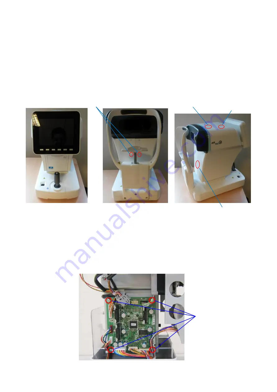
12–1 Replacement of the main unit cover unit, the 3 axes control board ASSY
1)
Remove the total of 6 fixing screws that are placed one each on the chin rest side and 2
each on the front side vertically of the main unit cover L and R.
2)
The main unit cover L and R are assembled with internal claws (3 places). Press around
Tab1 as thrusting internally with a thumb and pull them up to the direction of A.
3)
In case of replacement of the main unit cover, replace it with the backward process.
4)
In case of replacement of the 3 axes control board replacement, remove all of the harness
that are connected to the 3 axes control board ASSY. Unscrew 4 fixing screws of 3 axes
control board ASSY and remove the ASSY.
5)
This is the end of disassembling process. Assemble the 3 axes control board with the
backward process of disassembly.
Fixing screws
Fixing Screw
Tab 2
Tab 1
Tab 3
Summary of Contents for AKR 750
Page 1: ...Auto kerato refractometer Maintenance Manual V1 09 2016 ...
Page 6: ...4 Block Diagram ...
Page 7: ......
Page 8: ...8 ...
Page 66: ...65 ...


