

PILATUS
TURBO
PORTER
INSTRUCTIONS www.estarmodels.com
z
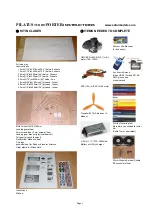
KIT INCLUDES
z
ITEMS NEEDED TO COMPLETE
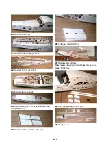
Full size plan
Lasercut parts
1.5mm(1/16”)xL570mm(22.4”) balsa : 5sheets
1.5mm(1/16”)xL360mm(14.2”) balsa : 5sheets
3.0mm(1/8”)xL600mm(24”) balsa : 3sheets
3.0mm(1/8”)xL330mm(13”) balsa : 3sheets
5.0mm(3/16”) xL600mm(24”) balsa : 2ea
1.8mm(5/64”)xL100mm(4”) plywood :1sheet
3.0mm(1/8”)xL300mm(12”) plywood :1sheet
3.0mm(1/8”)xL600mm(24”) plywood :1sheet
Motor mount 10x10x100mm
Landing gears(4ea)
3mm screws(4ea), 2mm screws(14ea)
Landing gear bracket (plywood lasercut)
Tail gear (plywood lasercut)
Neodymium Manetics (4ea)
CA hinge
pushrods(4ea) for Rudder, Elevator, Ailerons
Clear plastic for Windshield
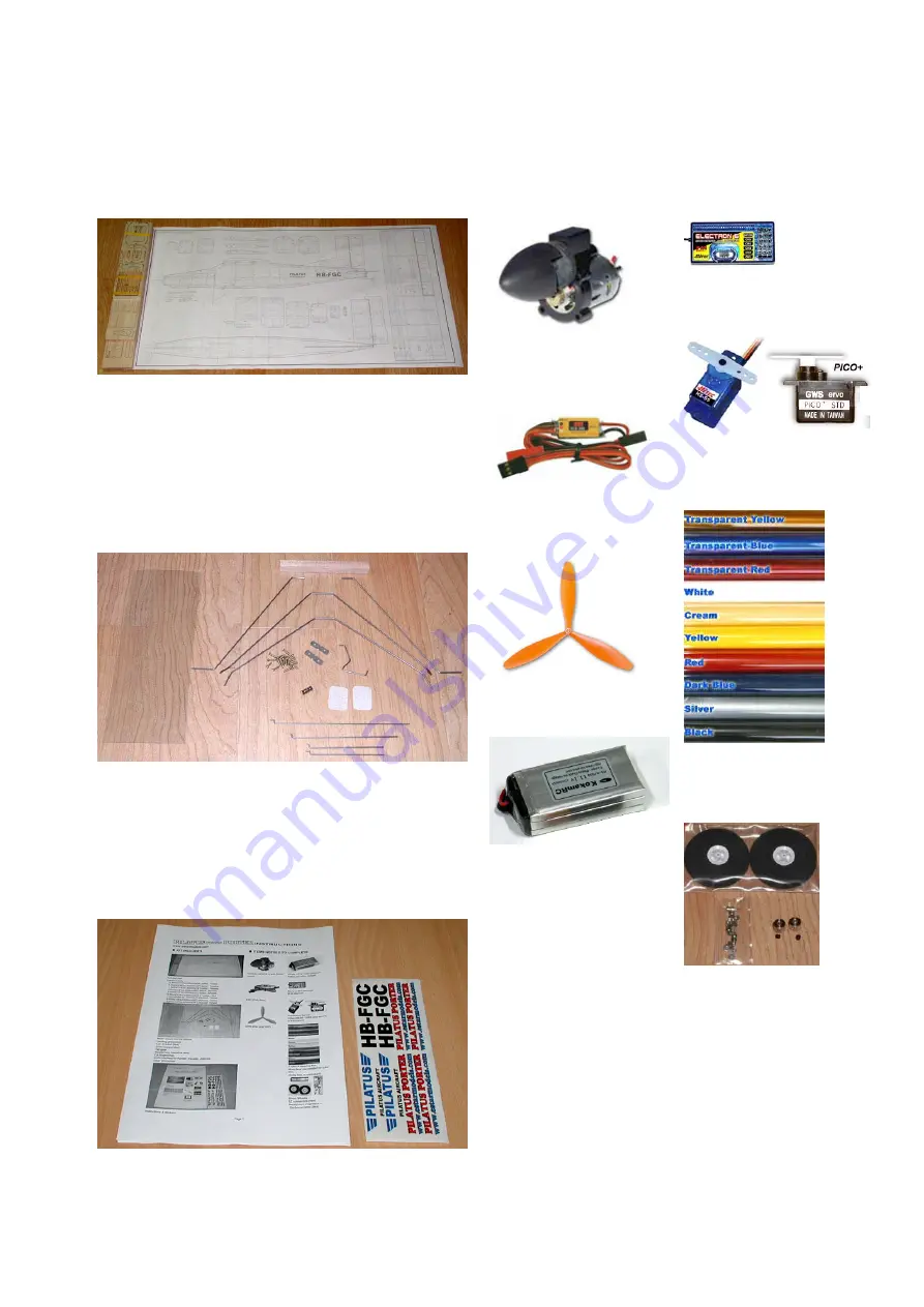
Instructions
Stickers.
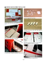
GWS EPS-400C-DS(3:1) or BL
motor (100~150W)
ESC (15A) or ESC for BL motor
Propeller 9070 (2-blades or 3-
blades)
Li-Poly 11.1V 1700~1800mAh
Battery w/Li-Poly charger
Micro or Mini Receiver
(4~6 channel)
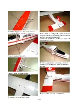
4 submicro Servos
(Hitec HS-55 / Futaba S3108 /
GWS pico servos,
or equivalant)
3 rolls of covering film.
More films you needed for color
trim.
(Solite film, or equivalant)
55mm Wheels & wheel Collars
EZ connectors (4ea)
Page 1


