ProNet series AC servo system User’s manual V.1.08
- 146 -
Para
Para
Para
Para....
No.
No.
No.
No.
Description
Description
Description
Description
Setting
Setting
Setting
Setting
Validation
Validation
Validation
Validation
Control
Control
Control
Control
Mode
Mode
Mode
Mode
Func tion
Func tion
Func tion
Func tion and
and
and
and Meaning
Meaning
Meaning
Meaning
llows:
0
:
S-ON
1
:
P-CON
2
:
P-OT
3
:
N-OT
4
:
ALMRST
5
:
CLR
6
:
P-CL
7
:
N-CL
8
:
G-SEL
9
:
JDPOS-JOG+
A
:
JDPOS-JOG-
B
:
JDPOS-HALT
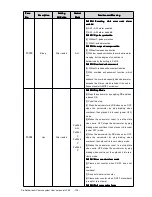
Pn510
Allocate
input
port
to
signal,
one
port
with
four bits(hex)
After restart
P
,
S
,
T
Pn511
Output signal
allocation
After restart
P
,
S
,
T
Pn511.0 corresponding port CN1_11
,
CN1_12
Pn511.1 corresponding port CN1_05
,
CN1_06
Pn511.2 corresponding port CN1_09
,
CN1_10
Corresponding signal of each data is shown as
follows:
0
:
COIN/VCMP
1
:
TGON
2
:
S-RDY
3
:
CLT
4
:
BK
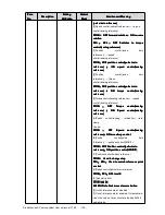
Pn512
Bus control input
node
low-bit
enabled
Immediately
P
,
S
,
T
Bus communication input port enabled:
[0]
:
Disabled
[1]
:
Enabled
Pn512.0
�
CN1_14
Pn512.1
�
CN1_15
Pn512.2
�
CN1_16
Pn512.3
�
CN1_17
Pn513.0
�
CN1_39
Pn513.1
�
CN1_40
Pn513.2
�
CN1_41
Pn513.3
�
CN1_42
Pn513
Bus control input
node
low-bit
enabled
Immediately
P
,
S
,
T
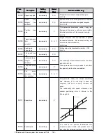
Pn514
Input port filter
Immediately
P
,
S
,
T
It is used to set input port filter time. The signal
will be lagged if the parameter setting is too high.
Pn515
Reserved
P
,
S
,
T
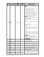
Pn516
Input port signal
inversion
Immediately
P
,
S
,
T
[0]
:
Does not inverse signal.
[1]
:
Inverses signal
Pn516.0
�
CN1_14 inversion
Pn516.1
�
CN1_15 inversion
Pn516.2
�
CN1_16 inversion
Pn516.3
�
CN1_17 inversion
Pn517.0
�
CN1_39 inversion
Pn517.1
�
CN1_40 inversion
Pn517.2
�
CN1_41 inversion
Pn517
Input port signal
inversion
Immediately
P
,
S
,
T


