Chapter 4
Operation
- 43 -
(2)Operating
(2)Operating
(2)Operating
(2)Operating Procedure
Procedure
Procedure
Procedure in
in
in
in Speed
Speed
Speed
Speed Control
Control
Control
Control Mode
Mode
Mode
Mode (Pn005=H.
(Pn005=H.
(Pn005=H.
(Pn005=H.□□
□□
□□
□□0
0
0
0□
□
□
□))))
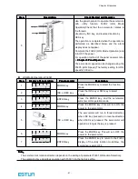
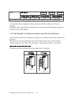
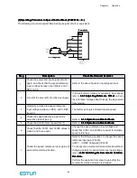
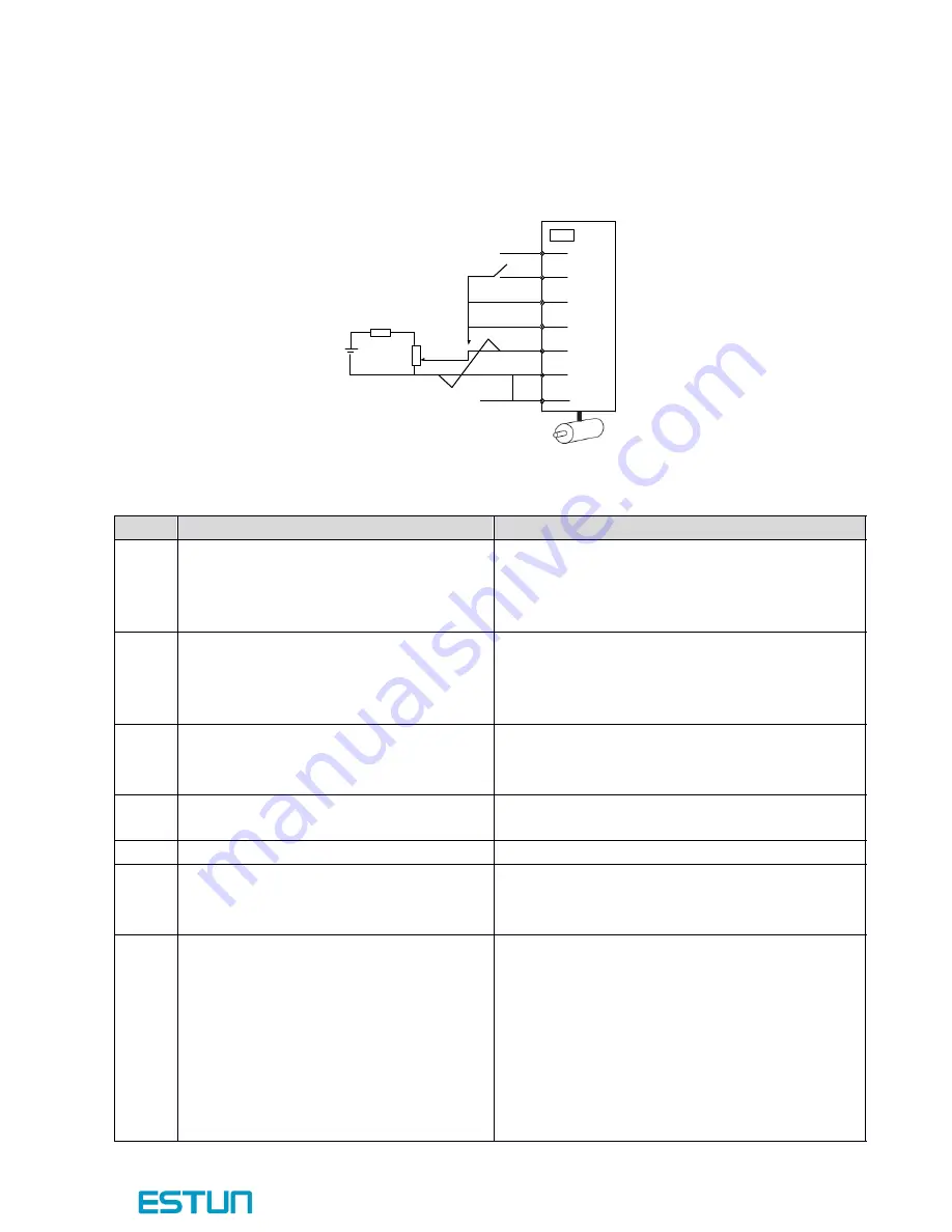
The following circuit is required: External input signal circuit or equivalent.
Step
Step
Step
Step
Description
Description
Description
Description
Check
Check
Check
Check Method
Method
Method
Method and
and
and
and Remarks
Remarks
Remarks
Remarks
1
Check the power and input signal circuits
again, and check that the speed reference
input (voltage between the V-REF+ and V-
REF-) is 0V.
Refer to the above figure for input signal circuit.
2
Turn ON the servo ON (/S-ON) input signal.
If the servomotor rotates at extremely slow speed,
refer to
4.5.3
4.5.3
4.5.3
4.5.3 Adjusting
Adjusting
Adjusting
Adjusting Reference
Reference
Reference
Reference Offset
Offset
Offset
Offset
,
and use
the reference voltage offset to keep the servomotor
from moving.
3
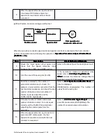
Generally increase the speed reference
input voltage between V-REF+ and V-REF-
from 0 V.
The factory setting is 6V/rated rotation speed.
4
Check the speed reference input to the
servodrive (Un001[min
-1
])
Refer to
5.1.6
5.1.6
5.1.6
5.1.6 Operation
Operation
Operation
Operation in
in
in
in Monitor
Monitor
Monitor
Monitor Mode
Mode
Mode
Mode
.
5
Check the Un000 (motor speed [min
-1
])
Refer to
5.1.6
5.1.6
5.1.6
5.1.6 Operation
Operation
Operation
Operation in
in
in
in Monitor
Monitor
Monitor
Monitor Mode
Mode
Mode
Mode
.
6
Check that the Un001 and Un000 values in
steps 4 and 5 are equal.
Change the speed reference input voltage and
check that Un001 and Un000 are equal for multiple
speed references.
7
Check the speed reference input gain and
servomotor rotation direction.
Refer to the following equation to change the speed
reference input gain (Pn300).
Un001
=
(V-REF Voltage)[V]×Pn300
To change the servomotor rotation direction without
changing polarity for speed reference input voltage,
refer to
4.3.2
4.3.2
4.3.2
4.3.2 Switching
Switching
Switching
Switching the
the
the
the Servomotor
Servomotor
Servomotor
Servomotor Rotation
Rotation
Rotation
Rotation
Direction.
Direction.
Direction.
Direction.
Perform the operation from step 2 again after the
servomotor rotation direction is changed.
+2 4 V
/S-O N
P-O T
N-O T
1
1 7
1 6
1 4
1 3
2
3
V-R E F +
V-R E F -
A G N D
C N 1
V-R E F +
V-R E F -
0V
Servo d rive
Servo d rive
Servo d rive
Servo d rive
M a x
M a x
M a x
M a x. . . . Vo ltag e
Vo ltag e
Vo ltag e
Vo ltag e ((((1 2
1 2
1 2
1 2 V
V
V
V))))

