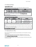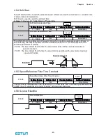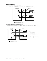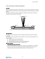
Chapter 4
Operation
- 73 -
(3)Procedure
(3)Procedure
(3)Procedure
(3)Procedure for
for
for
for Setting
Setting
Setting
Setting the
the
the
the Electronic
Electronic
Electronic
Electronic Gear
Gear
Gear
Gear Ratio
Ratio
Ratio
Ratio
Use the following procedure to set the electronic gear ratio.
(4)Electronic
(4)Electronic
(4)Electronic
(4)Electronic Gear
Gear
Gear
Gear Ratio
Ratio
Ratio
Ratio Setting
Setting
Setting
Setting Examples
Examples
Examples
Examples
The following examples show electronic gear ratio settings for different load configurations.
Reduce the fraction (both numerator and denominator) if the calculated result will not be within the setting range.
For example, reduce the above numerators and denominators by four or other numbers to obtain the final results in step
7 and complete the settings.
Step
Step
Step
Step
Operation
Operation
Operation
Operation
Description
Description
Description
Description
1
Check machine specifications.
Check the deceleration ratio, ball screw pitch and pulley
diameter.
2
Check the number of encoder
pulses.
Check the number of encoder pulses for the servomotor used.
3
Determine the reference unit used.
Determine the reference unit from the host controller,
considering the machine specifications and positioning
accuracy.
4
Calculate the travel distance per load
shaft revolution.
Calculate the number of reference units necessary to turn the
load shaft one revolution based on the previously determined
reference units.s
5
Calculate the electronic gear ratio.
Use the electronic gear ratio equation to calculate the ratio
(B/A).
6
Set parameters.
Set parameters using the calculated values.
Step
Step
Step
Step
Operation
Operation
Operation
Operation
Load
Load
Load
Load Configuration
Configuration
Configuration
Configuration
Ball
Ball
Ball
Ball Screw
Screw
Screw
Screw
Disc
Disc
Disc
Disc Table
Table
Table
Table
Belt
Belt
Belt
Belt and
and
and
and Pulley
Pulley
Pulley
Pulley
1 7
1 7
1 7
1 7 ----bit e nc ode r
bit e nc ode r
bit e nc ode r
bit e nc ode r
Ball sc r e w pitc h
Ball sc r e w pitc h
Ball sc r e w pitc h
Ball sc r e w pitc h
:
6
6
6
6m m
m m
m m
m m
R eference unit
R eference unit
R eference unit
R eference unit
:
0
0
0
0....0 0 1
0 0 1
0 0 1
0 0 1 m m
m m
m m
m m
Load shaft
Load shaft
Load shaft
Load shaft
R eference unit
R eference unit
R eference unit
R eference unit
:
0
0
0
0....1
1
1
1
º
Lo a d s ha ft
Lo a d s ha ft
Lo a d s ha ft
Lo a d s ha ft
1 7
1 7
1 7
1 7 ----bit enco der
bit enco der
bit enco der
bit enco der
D ecelera tio n ra tio
D ecelera tio n ra tio
D ecelera tio n ra tio
D ecelera tio n ra tio
: : : :
3
3
3
3
:
1
1
1
1
R eference unit
R eference unit
R eference unit
R eference unit
:
0
0
0
0....0 1
0 1
0 1
0 1 m m
m m
m m
m m
Load shaft
Load shaft
Load shaft
Load shaft
D eceleration ratio
D eceleration ratio
D eceleration ratio
D eceleration ratio ::::
2
2
2
2
:
1
1
1
1
1 7
1 7
1 7
1 7 ----bit encoder
bit encoder
bit encoder
bit encoder
Pulley diam eter
Pulley diam eter
Pulley diam eter
Pulley diam eter ::::
Φ
Φ
Φ
Φ1 0 0
1 0 0
1 0 0
1 0 0 m m
m m
m m
m m
1
Check
machine
specifications.
Ball screw pitch:mm
Deceleration ratio:/1
Rotation angle per revolution
:360° eceleration ratio:3/1
Pulley diameter:100 mm
(pulley circumference:314 mm)
·Deceleration ratio:2/1
2
Encoder
17-bit:32768P/R
17-bit:32768P/R
17-bit:32768P/R
3
Determine the
rference unit
used
1 reference unit:
0.001mm(1μm)
1 reference unit:0.1°
1 reference unit:0.01mm
4
Calculate the
travel distance
per load shaft
revolution
6mm/0.001mm=6000
360°/0.1°=3600
314mm/0.01mm=31400
5
Calculate the
electronic gear
ratio
1
1
6000
4
32768
×
×
=
A
B
1
3
3600
4
32768
×
×
=
A
B
1
2
31400
4
32768
×
×
=
A
B
6
Set parameters
Pn201
131072
Pn201
393216
Pn201
262144
Pn202
6000
Pn202
3600
Pn202
31400
7
Final Result
Pn201
32768
Pn201
32768
Pn201
32768
Pn202
1500
Pn202
300
Pn202
3925


