Chapter 4 Operation
- 77 -
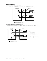
When the external power supply is used, the circuit will be isolated by a photocoupler. When the
servodrive internal power supply is used, the circuit will not be isolated.
Note
Note
Note
Note
:
When the open-collector output is ued, input signal noise margin lowers. When a position error
caused by the noise occurs, set the parameter Pn006.3.
(3)Position
(3)Position
(3)Position
(3)Position Control
Control
Control
Control Block
Block
Block
Block Diagram
Diagram
Diagram
Diagram
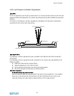
A block diagram for position control is shown as below.
Differential
Feed forw ard
B
A
Feed forward
filter time
constant
O ffs e t
Positioning
complete
Current loop
Speed loop
K P
Error counter
Smoothing
×1
×2
×4
dividing
×4
B
A
S e r vod r ive
S e r vod r ive
S e r vod r ive
S e r vod r ive ((((in p osition con trol
in p osition con trol
in p osition con trol
in p osition con trol ))))
P n 1 1 2
P n 2 0 1
P n 2 0 2
P n 1 1 5
P n 1 1 1
P n 5 0 0
P n 0 0 4.2
P n 2 0 4
P n 2 0 1
P n 2 0 2
P n 2 0 0
Reference pulse
PG signal output
P n 1 0 4
M
P G
Servomotor
Encoder
-
+
+
+
+
Host controller
*
3 4
3 0
C N 1
*
Represents twisted -pair wires .
P U LS
P P I
3 1
3 4
3 2
3 3
/P U LS
P P I
S I G N
/S I G N
1 5 0
Ω
T r 1
1.5V m ax. a t O N
2k
Ω
Ser vodr ive
photocoupler
2k
Ω
1 5 0
Ω
+2 4 V
+2 4 V


