background image

MC404-Z 

Document Version: 1.05 

© 2021 All rights reserved. 

18 


Firmware 

The MC404-Z comes pre-installed with the firmware version which was released to 
production at the time of manufacture.  Newer versions may be available to download from 
the Trio website and it is recommended to check if an update is available before using the 
Motion Coordinator for an application. 
New firmware can be installed using Motion Perfect.  Click the Controller menu and select 

Load Firmware 

….


The firmware file must be extracted from the zip folder before it can be 

used.  Firmware file names start MC404Z_ and have the extension .out.  Do not attempt to 
load firmware designed for a different Motion Coordinator type. 

Firmware recovery 

Firmware can be re-installed without using Motion Perfect by adding the firmware file to a 
micro SD card so that the MC404-Z will automatically re-load the firmware at power-on. 
Format the micro SD card to FAT 32, rename the firmware file to r_406.out and copy the file 
on to the SD card.  Insert the card into the slot on the Motion Coordinator and power up.  
The Red LED will flash during the firmware loading process.  When the Red LED becomes 
steady it will be possible to re-connect to the MC404-Z via Ethernet. 

All applications programs will be deleted when the new firmware is installed 

Dimensions 


Summary of Contents for Trio MC404-Z

Page 1: ...USER MANUAL MC404 Z 4 AXIS MOTION COORDINATOR...

Page 2: ...o or Stepper Motor Drive A Servo or Stepper Drive which is used for controlling the Motor Servo System A Servo Control System that includes a Motor a Drive a host controller Motion Coordinator and per...

Page 3: ...20 1 00 Draft 12 Nov 2020 1 01 Update 1 minor edits 27 Nov 2020 1 02 Update 2 added EMC section and panel mount dimensions 22 Dec 2020 1 03 Updated product comparison table 28 May 2021 1 04 Added AOUT...

Page 4: ...ge without notice Despite every effort in a manual of this scope errors and omissions may occur Therefore Trio Motion Technology Ltd cannot be held responsible for any malfunctions or loss of data as...

Page 5: ...must ensure there is no possibility of injury to any person or damage to machinery Control systems especially during installation can malfunction or behave unexpectedly Users must ensure that in all c...

Page 6: ...ors 9 Connections to the MC404 Z 9 Serial connections 9 CANbus connections 9 Amplifier enable Watchdog relay output 10 Analogue I O 10 Axis ports 10 Registration 12 I O connector 1 12 I O connector 2...

Page 7: ...1 All rights reserved 6 Electromagnetic Compatibility 24 Intended conditions of use 24 EMC Considerations 24 Product specific requirements 24 Recommended Installation 26 Surge Protection 26 Surge prot...

Page 8: ...and then may be set to run standalone if an external computer is not required for the final system Programs and data are stored directly to FLASH memory thus eliminating the need for battery backed s...

Page 9: ...AY and IP _ NETMASK to their default values press the IP reset button located next to the SD card slot and power cycle the controller while keeping the button pressed The factory default IP address is...

Page 10: ...axes are enabled and ready to move A flashing red LED indicates that one or more axes are in error Connections to the MC404 Z Ethernet port connection RJ45 socket 10 100 base_T The Ethernet port is th...

Page 11: ...drive Axis ports The MC404 Z is designed to support pulse driven motor drives on the standard controller hardware All 4 axes are available as standard and no additional axis feature enable codes are r...

Page 12: ...Direction and Enable or A B and Enable Inputs for A B and Z incremental encoder or Clock and Data absolute encoders Pin Description 1 Step A 2 Step A 3 Direction B 4 Direction B 5 0V 6 Enable 7 Enabl...

Page 13: ...onnection screw should be applied to the lower mounting point for bonding the MC404 Z to ground 24V Output channels NPN Output channels 8 15 are NPN sinking outputs The output circuit has electronic o...

Page 14: ...solated therefore the 0V return MUST be connected to all peripheral devices In addition bond together the 0V 24V return terminals of all system components to minimise current flowing in the serial cab...

Page 15: ...drives that have pulse and direction inputs for motion also use a 24V enable input The WDOG connection pins 6 and 14 on the Auxiliary connector can be used to directly enable the drives The same sign...

Page 16: ...ng and system debug A PC running Microsoft Windows Windows 10 or later recommended is required Download Motion Perfect from www triomotion com and install on the PC Connection is via the Ethernet port...

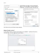
Page 17: ...P address Set an IP address in the same subnet as the MC404 Z Usually this will be 192 168 0 xxx Click OK and close the Ethernet setup dialogues Motion Perfect version 5 Launch Motion Perfect and sele...

Page 18: ...IP Reset button located next to the SD card slot while powering up the MC404 Z This will reset the IP_ADDRESS to 192 168 0 250 Motion Perfect in Synchronised connection mode The MC404 Z is capable of...

Page 19: ...re file names start MC404Z_ and have the extension out Do not attempt to load firmware designed for a different Motion Coordinator type Firmware recovery Firmware can be re installed without using Mot...

Page 20: ...to maintain the environmental temperature within the operating temperature range If clearance is allowed for cable connections there is no further limit on spacing next to other components that do no...

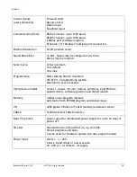
Page 21: ...sking Motion iX system IEC 61131 3 programming system Maximum 6 user processes Interpolation modes Linear 1 4 axes circular helical spherical CAM Profiles speed control software gearbox and linked mot...

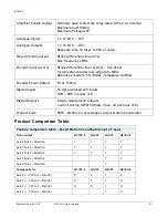
Page 22: ...Biss Encoder Power Output 5V at 150mA Digital Inputs 16 Opto isolated 24V inputs NPN PNP in banks of 8 Digital Outputs 8 Opto isolated 24V outputs Current sinking NPN 500 mA max 4A per bank of 8 Produ...

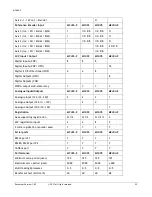
Page 23: ...ts NPN 8 Digital Outputs PNP WDOG output solid state relay Y Y Y Y Analogue Inputs Outputs MC403 Z MC403 MC405 MC404 Z Analogue Input 12 bit 0 10V 2 2 2 1 Analogue Output 12 bit 10V 2 4 Analogue Outpu...

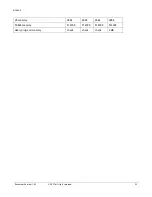
Page 24: ...MC404 Z Document Version 1 05 2021 All rights reserved 23 VR memory 4096 4096 4096 4096 TABLE memory 512000 512000 512000 512000 User program memory check check check 3 MB...

Page 25: ...se generators such as contactors solenoid coils and relays as far away as possible from the Motion Coordinator Where possible use solid state contactors and relays Fit suppressors across coils and con...

Page 26: ...ing 1 Maintain 150mm separation of parallel Class I and Class II cable IEC 61000 5 2 1997 2 Unless otherwise specified all cables must be 30m in length Proximity to source of disturbance 1 Place contr...

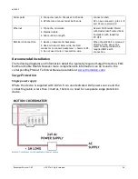
Page 27: ...ssis to PE 3 Do not use circular cross section wire When the MC404 Z is screwed directly to the panel the metal chassis provides the required EMC earth connection Recommended Installation The followin...

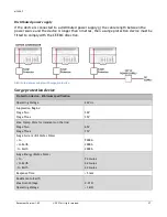
Page 28: ...directive Distributed power supply with surge protection Surge protection device Protection device Minimum specification Operating Voltage 24V dc Suppression Begins Stage Two Stage Three 30V 35V Max C...

Page 29: ...ecified with one extra wire to carry the 0V All serial cables must be terminated in the 15 pin auxiliary connector For best EMC performance clamp the screen of the serial cable where it enters the con...

Reviews: