background image

2 Connecting to the system

2 Connecting to the system

2.1 Location

The unit is intended for indoor installation only. After selecting the location, make sure

that it meets the following requirements:

1. The location must be free from excessive humidity and from flammable or corrosive vapours.

2. The unit must not be installed near high power electrical equipment, electrical machines or welding 

equipment.

3. The temperature in the location must not exceed 60ºC and should not be lower than

0ºC. Humidity should be within the range from 5% to 95%, with no vapour condensation

taking place.

2.2 Connecting internet module and configuration 

The equipment connection and configuration shall be completed in the following steps:

1. Log to 

igneo.pl

If you do not have your account at igneo.pl, register yourself. After registration you will receive an 

e-mail with an activation link. 

2. Add the equipment to your account clicking the “Add  the device” box in the right hand side corner. 

The PIN identifying the Internet Module is necessary for registration. The PIN is given on the label on  

the device.

3. Connect the Internet Module with the CAN cable to the boiler controller. It is recommended to 

connect the terminator with a jumper, if the Internet Module is on one of the ends of the CAN; in 

such a case also disconnect the terminator in the device that was at the end before connecting the  

Internet Module. 

4. Connect the Internet Module to the Internet slot. After connecting the device to the Internet, the LED 

on the right (looking from the front), on the RJ45, should be off. Use a crossed cable if it does not 

happen.

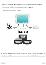
5. Connect the power supply to the 5V DC Internet Module. 

NOTE

. Connect the Internet Module in less than one hour from adding the device on the website

page  6

EN20141219

Summary of Contents for VIDENET

Page 1: ...Internet module VIDENET ...

Page 2: ...page 2 EN20141219 ...

Page 3: ...1 2 Components of the set 4 1 3 Handling of used equipment 4 1 4 Safety precautions 5 2 Connecting to the system 6 2 1 Location 6 2 2 Connecting internet module and configuration 6 3 Use 8 3 1 Signalling LEDs 8 4 Specifications 8 estyma electronics www estyma pl page 3 EN20141219 ...

Page 4: ...ly a weather forecast can be seen It is activated against ƫ entering your address in the se tings The equipment works only with controllers with the latest version of compatible software The module is not suitable for use with previous generation controllers or devices from other manufacturers The Internet router which the Internet Module is connected to through the network cable has to come with ...

Page 5: ...any objects into the unit through openings e g ventilation grills as this may cause short circuiting electric shock fire or damage to the unit Do not allow water humidity or dust to enter the unit as this may cause short circuiting electric shock fire or damage to the unit Provide adequate ventilation of the unit do not cover or block the ventilation grills and ensure that there is free flow of ai...

Page 6: ...gister yourself After registration you will receive an e mail with an activation link 2 Add the equipment to your account clicking the Add the device box in the right hand side corner The PIN identifying the Internet Module is necessary for registration The PIN is given on the label on the device 3 Connect the Internet Module with the CAN cable to the boiler controller It is recommended to connect...

Page 7: ...iler online at igneo pl Diagram of the Internet Module connection The router must have the DHCP so that the equipment can establish Internet connection NOTE Documentation of the igneo pl Internet service functions is available after logging in the Help tag in the top right hand side corner of the screen or directly at http igneo pl help estyma electronics www estyma pl page 7 EN20141219 ...

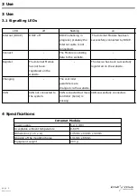
Page 8: ...as not been registered on the website The device has been successfully registered on the website Changing The controller parameters are changed via the website CAN CAN not connected to the system CAN connected but main controller boiler is missing CAN successfully connected 4 Specifications Internet Module Power supply 5 0 V DC Acceptable ambient temperature 0 60 C Dimensions l x h x w 145mm x 94m...

Page 9: ...Manufactured by Estyma electronics al Lipowa 4 11 500 Giżycko POLAND tel 48 87 429 86 75 fax 48 87 429 86 75 biuro estyma pl www estyma pl estyma electronics www estyma pl page 9 EN20141219 ...

Reviews: