background image

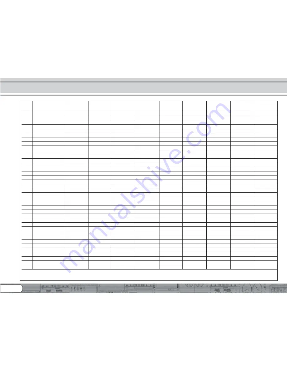
40

vaule

1

2

4

8

16

32

64

128

FS(f)

stand forward

129

FS(r)

stand backward

132

FF(f)

drive forward

135

FF(r)

drive  backward

138

F0

light forward

141

1

F0

light backward

144

2

F1

key F1 forward

147

4

F1

key F1 backward

150

4

F2

key F2 forward

153

8

F2

key F2 backward

156

8

F3

key F3 forward

159

F3

key F3 backward

162

F4

key F4 forward

165

F4

key F4 backward

168

F5

key F5 forward

171

16

F5

key F5 backward

174

16

F6

key F6 forward

177

32

F6

key F6 backward

180

32

F7

key F7 forward

183

64

F7

key F7 backward

186

64

F8

key F8 forward

189

128

F8

key F8 backward

192

128

F9

key F9 forward

195

F9

key F9 backward

198

F10

key F10 forward

201

F10

key F10 backward

204

F11

key F11 forward

207

F11

key F11 backward

210

F12

key F12 forward

213

F12

key F12 backward

216

F13

key F13 forward

*

219

F13

key F13 backward

*

222

F14

key F14 forward

*

225

F14

key F14 backward

*

228

F15

key F15 forward

*

231

F15

key F15 backward

*

234

Funct.- Description

Control

Headlight

Back-up lights

AUX 1

AUX 2

AUX 3

AUX 4

AUX 5

AUX 6

button

CV  A

(if available)

(if available)

(if available)

(if available)

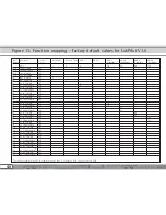
Figure 13: Function mapping - factory default values for LokPilot V3.0

*

 except for LokPilot micro V3.0, LokPilot micro V3.0 DCC, LokPilot Fx V3.0, LokPilot Fx micro V3.0

Summary of Contents for LokPilot Fx micro V3.0

Page 1: ...r manual 7 edition November 2009 LokPilot V3 0 LokPilot V3 0 DCC LokPilot V3 0 M4 LokPilot XL V3 0 LokPilot micro V3 0 LokPilot micro V3 0 DCC LokPilot Fx V3 0 LokPilot Fx micro V3 0 LokPilot V3 0 P N 51978 ...

Page 2: ... 9 6 Installing the Decoder 6 Installing the Decoder 6 Installing the Decoder 6 Installing the Decoder 6 Installing the Decoder 10 10 10 10 10 6 1 Requirements for Installation 10 6 2 Installing the Decoder 10 6 3 Locomotives with 8 pole NEM 652 Interface 10 6 4 Locomotives with 6 pole NEM 651 Interface 11 6 5 Locomotives with 21MTC Interface 12 6 5 1 Connecting C Sine motors SoftDrive Sinus 12 6 ...

Page 3: ...n Operating Modes 31 10 4 1 Changing from Digital to Analogue DC 31 10 4 2 Changing from Digital to Analogue AC 31 10 4 3 Changing from Analogue to Digital directional bit 31 10 4 4 Changing from Digital to Digital 31 10 4 5 Changing modes with Analogue Mode turned off 32 10 5 Brake Sectors 32 10 5 1 DC Brake Mode 32 10 5 2 Märklin Brake Mode 32 10 5 3 Selectrix Diode Brake Sector 33 10 6 Constant...

Page 4: ...ulse Sequence Mode 43 12 6 Swiss Headlight Mode 43 13 Decoder Reset 13 Decoder Reset 13 Decoder Reset 13 Decoder Reset 13 Decoder Reset 43 43 43 43 43 13 1 With DCC Systems or 6020 6021 43 13 2 With Märklin systems M4 decoders only 43 13 3 With the ESU LokProgrammer 43 14 Special Functions 14 Special Functions 14 Special Functions 14 Special Functions 14 Special Functions 44 44 44 44 44 14 1 Direc...

Page 5: ...nual carefully Although the LokPilot has been design as a robust device an incorrect connection may lead to faults or even to the destruction of the device Avoid any costly experiments Important notes The LokPilot is exclusively intended for use with model train layouts only It may only be operated with the components listed here Any other use is not permitted Any wiring has to be carried out whil...

Page 6: ...The Members of the LokPilot Family Once more ESU introduced an even more advanced version of the popular LokPilot decoder with its third generation LP V3 0 All LokPilot V3 0 decoders complement the excellent properties of their predecessors and expand their capabilities by further functions These developments further improve the driving characteristics the operational reliability and the flexibili...

Page 7: ...atic recognition Ok RailCom option Ok Ok Ok Ok Ok Ok Ok continuous motor current 0 75A 0 75A 1 1A 1 1A 1 1A 3 0A function output current 2 140mA 2 140mA 4 250 mA 4 250mA 4 250mA 8 600mA 4 140mA 6 250mA integrated PowerPack buffer capacitor connection type 6 pin 6 pin 6 pin 6 pin 8 pin 6 pin 21MTC 8 pin 6 pin 8 pin 21MTC screwing 6 pin 8 pin 21MTC direct harness direct harness harness harness harne...

Page 8: ...he pure DCC decoders are true multi protocol decoders with automatic detection of the operating mode on the fly The decoder analyses the track signal and filters out the part that is reserved for it Changing from digital to analogue and back represents no problem whatsoever This is important in case your storage fiddle yard still works in analogue mode Furthermore all LokPilot decoders support the...

Page 9: ...times can be separately adjusted and switched and of course you can switch the shunting mode The brightness of all function outputs can be separately set and allocated to the desired function buttons function mapping There is a wide range of options dimmer flickering firebox gyro light and mars light flash and double flash blinker and alternate blinker as well as switch functions with timers e g f...

Page 10: ...ive tape or some just a little hot glue 6 3 Locomotives with 8 pole NEM 652 Interface Some LokPilot V3 0 decoders are supplied with an 8 pole interface as per NEM 652 refer to Fig 1 Installation in locomotives with this interface is particularly easy Remove the locomotive body Please observe the instructions in the manual of your locomotive Remove the dummy plug from the socket and keep it in a su...

Page 11: ...t track connection black 5 headlight white 6 rear light yellow 52687 LokPilot micro V3 0 52684 LokPilot micro V3 0 blue common pole right motor terminal left motor terminal right track connection left track connection headlight rearlight soldering pad AUX1 Logic level 52686 LokPilot micro V3 0 52685 LokPilot micro V3 0 right motor terminal left motor terminal right track connection left track conn...

Page 12: ...th the decoder Do not apply too much pressure when inserting the plug The decoder must go in without force Check if the decoder sits correctly 6 5 1 Connecting C Sine motors SoftDrive Sinus The LokPilot decoder cannot drive the newer Märklin models with C Sine motors also called SoftDrive Sinus directly To facilitate this a circuit board supplied with the locomotive is required Märklin uses the 21...

Page 13: ...ite yellow Head Lights Rear Lights chassis orange gray red black white yellow blue optional instead of chassis connection violet green yellow white AUX2 AUX1 Rear Light Head Light gray orange motor red chassis 52610 LokPilot V3 0 52611 LokPilot V3 0 DCC 61600 LokPilot V3 0 M4 violet orange red yellow blue green white black gray R black Figure 4 Wiring Diagram for LokPilot V3 0 LokPilot V3 0 DCC Lo...

Page 14: ...gram for LokPilot XL V3 0 wiring example left track connection right track connection Common Pole AUX6 AUX5 AUX4 AUX3 AUX2 AUX1 green yellow white AUX1 Rear Lights Head Lights red chassis 52620 LokPilot Fx V3 0 violet orange red yellow blue green white black gray R black Figure 7 Wiring diagram for LokPilot Fx V3 0 wiring example violet AUX2 orange AUX3 gray AUX4 ...

Page 15: ... the chassis the motor leads must be positively potential free in other words the may not have any contact to the chassis or body or the wheels and wheel contacts It is particularly easy to overlook such connections in Fleischmann locomotives Make notes of which motor lead connects the motor with the right and the left wheel contact This avoids mistakes and assures that your locomotive runs in the...

Page 16: ...urrent still be too high perhaps due to a short circuit the same procedure starts again When using light bulbs incandescent lamps please note the following they draw a very high inrush current when they are switched on that becomes lower after a few moments Therefore it can happen with 12V bulbs that the headlights flash briefly during switch on and then extinguish due to the overload protection o...

Page 17: ...esides the 4 standard outputs namely AUX3 and AUX4 Since they are pure logic outputs it is not possible to connect any external loads directly External power transistors are required Connect AUX3 and AUX4 via the interface there are no wire leads In terms of their functionality AUX3 and AUX4 are equal to the other outputs 6 7 3 2 LokPilot Fx V3 0 The LokPilot Fx V3 0 offers up to 6 function output...

Page 18: ...sed by inappropriate soldering Consider carefully if you really need that capacitor 6 8 1 All LokPilot H0 You can connect two larger capacitors as per the circuit in Fig 11 One buffers the motor output the smaler capacitor supports the microcontroller of the decoder The capacitor is charged via a resistor 100 Ohms thus preventing the digital system from interpreting the charging current as short c...

Page 19: ...6 if available LokPilot Fx V3 0 F1 switches output AUX1 F2 switches output AUX2 F3 switches output AUX3 F4 switches output AUX4 Does the locomotive move in both directions Does the indicated direction of travel correspond with the actual one If not are the motor leads swapped or is the 8 pole plug inserted the wrong way round Switch on the lights do they work properly If you have installed a LokPi...

Page 20: ... at all The lights keep switching on and off dependent on the speed step In this case make sure that the speed step settings of decoder and command station are the same 7 2 1 2 Auto detection of DCC Speed Steps LokPilot decoders implement auto detection to avoid the above problem We have tested this with the following systems ESU ECoS Bachmann E Z Command Dynamis ROCO Lokmaus2 and Lokmaus3 Uhlenbr...

Page 21: ... how to set the address 7 2 3 Selectrix Mode LokPilot V3 0 LokPilot micro V3 0 LokPilot XL V3 0 You may operate the LokPilot with any Selectrix compatible command station with access to the functions lights and F1 For programming any parameters you must use the DCC programming mode It is not possible to program it with a pure Selectrix system Any changes programmed in DCC are also valid for operat...

Page 22: ...til the locomotive has stopped prior to changing direction Never issue the Change of Direction command to a moving locomotive This could lead to damaged gears We cannot recommend the use of the old blue Märklin transformers that where originally designed for 110 220 Volt Depending on their age and their tolerance range the pulse for changing direction could be too high in case of increased mains v...

Page 23: ...on Variable and indicates that the storage cells described above are not only variable but they also determine the behaviour of the decoder 8 1 1 1 Standardisation in the NMRA The NMRA National Model Railroad Association has defined which CVs determine certain parameters of a decoder The DCC standard allocates fixed numbers for certain CVs adherence is obligatory This greatly simplifies things for...

Page 24: ...e memory spaces the so called M4 configuration area of the decoder Generally M4 only permits access via the command station This method has only one drawback How can the owners of other command stations that are not M4 capable access the configuration area This is facilitated by means of a register concept that is somewhat similar to the NMRA DCC CVs Unfortunately this does not provide access to a...

Page 25: ... LokPilot micro V3 0 LokPilot micro V3 0 DCC LokPilot XL V3 0 LokPilot Fx V3 0 LokPilot Fx micro V3 0 The owners of an ESU ECoS can comfortably program LokPilot decoders ECoS has a library of Decoder Profiles that help you to program decoders with the graphic display All CVs are stored in the decoder profile thus enabling the ECoS to read them and to display them on the screen Chapter 16 5 of the ...

Page 26: ...r the new value for the desired CV e g 15 two digits For confirmation activate the change of direction routine now the lights light up for about one second Then you can enter other CVs as desired Selecting 80 allows you to exit the programming mode Alternately you can switch off the track voltage and then on again press the Stop button on the 6021 then the Go button 8 2 3 3 Long mode You access th...

Page 27: ...he locomotive Ex 3 3 is shown as active on the display By pressing the MENU ESC button you can now change any of the settings such as name address etc in the heading CHANGE LOCOMOTIVE The last function shown is Register Programming REG Select this for writing CVs Then select the CV called REG on the Mobile Station and then the desired value and confirm by pressing the change of direction button Th...

Page 28: ...t address that is stored in CV 1 In DCC mode the permitted values range from 1 to 127 In order to enable the decoder to listen to the short address you must delete bit 5 in CV 29 Some digital systems e g ROCO Lokmaus2 Lenz digital plus Lenz compact only support the values 1 99 as short address 9 2 Long Addresses in DCC Mode LokPilot V3 0 LokPilot V3 0 DCC LokPilot micro V3 0 LokPilot micro V3 0 DC...

Page 29: ... mode and ignores Motorola commands 9 4 Addresses in the M4 Mode LokPilot V3 0 M4 The M4 systems also use addresses for directing commands to a locomotive However the addresses are allocated automatically when the decoder first reports to the central unit Neither can the user program these addresses nor can he read them 10 Adapting the Driving Characteristics 10 1 Acceleration and Deceleration Acc...

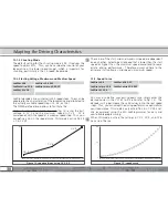
Page 30: ...peed are dependent on each other Selecting a mid speed that is lower than the start speed or higher than the maximum speed could lead to some erratic driving performance Therefore always adhere to the principle start voltage mid speed maximum speed 10 3 Speed Curve LokPilot V3 0 LokPilot V3 0 DCC LokPilot micro V3 0 LokPilot micro V3 0 DCC LokPilot XL V3 0 You may also define your own speed curve ...

Page 31: ...ctional bit When entering the digital sector the locomotive compares the current direction of movement with the digital signals arriving via the track If the actual direction matches the one as per the digital signal the locomotive continues onwards at a speed corresponding with the digital signals Does the direction not match the commands from the digital system then the behaviour depends on the ...

Page 32: ...refer to chapter 10 5 10 5 Brake Sectors Brake sectors have the purpose to slow down the locomotive independently from the commands issued by the command station Frequently this function serves for stopping a train in front of a red signal If a LokPilot detects a brake command it will slow down with the programmed deceleration and then stop After this enforced stop the locomotive will accelerate a...

Page 33: ...The higher the value in CV 254 the longer is the brake distance Simply make some trials on a test track in order to find the values best suited to your locomotive If CV 254 is set to 0 then the normal time mode as per chapter 10 1 will automatically turn on The constant brake distance is only active in brake sectors When you turn the throttle back to 0 the locomotive will slow down as per the valu...

Page 34: ...okPilot XL V3 0 4th generation load compensation enables LokPilot decoders to execute precise motor control Even with the default settings most locomotives run perfectly 11 1 Adjusting Load Compensation Should you find after programming and doing the initial test that the locomotive does not run smoothly particularly at low speed or that the locomotive jerks a little after having stopped or if you...

Page 35: ...ps until the locomotive runs smoothly at speed step 1 With some motors it may be necessary to set the starting voltage to a value between 4 and 6 in order to arrive at good results Motor Control type of motor type of motor type of motor type of motor type of motor r r r r remarks emarks emarks emarks emarks CV 2 CV 2 CV 2 CV 2 CV 2 CV 53 CV 53 CV 53 CV 53 CV 53 CV 54 CV 54 CV 54 CV 54 CV 54 CV 55 ...

Page 36: ...uence on the speed then you should reduce the value of CV 53 Reduce the value by 5 8 and test the locomotive again Repeat this process until the locomotive just reaches its maximum speed when the throttle is fully open 11 2 Turning off Load Compensation LokPilot V3 0 LokPilot V3 0 DCC LokPilot micro V3 0 LokPilot micro V3 0 DCC LokPilot XL V3 0 Occasionally it may be beneficial to turn off load co...

Page 37: ...e hill The desired degree of load control influence is set in CV 56 It is particularly meaningful to reduce the influence of load control whenever you run consists This allows for better driving properties of all locomotives in the consist 11 5 Settings for the C Sinus Motor LokPilot decoders with the 21MTC interface can drive the new C Sinus motors indirectly via the circuit board installed in th...

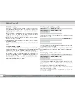
Page 38: ...l functions Each physical output must first be switched on and then linked to a function button Figure 17 on the following double page provides an overview about all possible combinations LokPilot micro V3 0 LokPilot micro V3 0 DCC LokPilot Fx V3 0 and LokPilot Fx micro V3 0 support the function buttons F0 to F12 the other LokPilot decoders F0 to F15 We will have a look at some examples in order t...

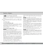
Page 39: ...igital couplers Subject to the type of coupler you must adjust certain settings 12 3 3 1 Pulse Mode for Telex In order to operate the Märklin Telex coupler we have created the Pulse function the brightness value takes on a special role in this case the value determines how long a function should remain switched The brightness value 0 means 0 5 seconds the value 15 corresponds to about 8 seconds Af...

Page 40: ... 64 F8 key F8 forward 189 128 F8 key F8 backward 192 128 F9 key F9 forward 195 F9 key F9 backward 198 F10 key F10 forward 201 F10 key F10 backward 204 F11 key F11 forward 207 F11 key F11 backward 210 F12 key F12 forward 213 F12 key F12 backward 216 F13 key F13 forward 219 F13 key F13 backward 222 F14 key F14 forward 225 F14 key F14 backward 228 F15 key F15 forward 231 F15 key F15 backward 234 Func...

Page 41: ...3 160 2 F3 163 2 F4 166 1 F4 169 1 F5 172 F5 175 F6 178 F6 181 F7 184 F7 187 F8 190 F8 193 F9 196 F9 199 F10 202 F10 205 F11 208 F11 211 F12 214 F12 217 F13 220 F13 223 F14 226 F14 229 F15 231 F15 235 Funct Control Acceleration Shunting Sound Dynamic Button CV B ON OFF mode On Off On Off brake ...

Page 42: ...t until it meets the column for AUX1 then you find a number in the header line above In our example the number is 4 Enter this value into CV 171 Then the F5 button will switch the output AUX1 Thus the function is programmed for forward travel Now enter the same values in CV 174 in order to activate the same for travelling in reverse Example 2 Blinker beacon on AUX2 and F6 You want to wire a blinke...

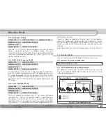
Page 43: ...LokPilot micro V3 0 LokPilot micro V3 0 DCC LokPilot XL V3 0 LokPilot Fx V3 0 LokPilot Fx micro V3 0 Function mapping enables you to set many different configurations The Swiss headlight mode is a good example We need a third lighting circuit that switches the left lower headlight of the A headlight configuration whenever the lights are turned on This third circuit must work independently form the...

Page 44: ...ot set then the locomotive will attempt to reach the previous speed as quickly as possible We recommend turning off this option since it overrules the effects of the programmed acceleration This option is actually only intended for operation with the 6020 since the 6020 does not transmit any commands after being switched on The default setting records the direction the status of the functions and ...

Page 45: ...n detect this command Thus the command station can find out the location of that particular locomotive CV information the decoder can provide feedback about all CV values to the command station per RailCom In future a programming track will not be necessary any more Meta data the decoder can transmit status information such as motor load current draw of the motor temperature etc to the command sta...

Page 46: ...ate 51967 comes in handy it has a socket for plugging in the LokPilot but also has solder points for connecting the original wiring of the locomotive This is ideal for converting Märklin locomotives 19 Support and assistance Your model train dealer or hobby shop is your competent partner for all questions regarding your LokPilot decoder In fact he is your competent partner for all questions around...

Page 47: ...021 Mobile Station or Central Station Ok Ok Ok Ok Ok M4 Programming procedure Ok Märklin brake section Ok Ok Ok Ok Ok Ok Brake on DC Roco brake section Ok Ok Ok Ok Ok Ok Ok Selectrix brake mode with diodes Ok Ok Ok Shunting mode Ok Ok Ok Ok Ok Ok RailCom Option by Firmwareupgrade Ok Ok Ok Ok Ok Ok Continuous motor load 0 75A 0 75A 1 1A 1 1A 1 1A 3 0A 4th generation back EMF control overload protec...

Page 48: ...the minimum speed of the engine 1 75 3 3 Acceleration This value multiplied by 0 869 is the time from stop to 0 64 8 maximum speed 4 Decelearation This value multiplied by 0 869 is the time from maximum 0 64 6 speed to stop brake time 5 Maximum speed Maximum speed of the engine 0 64 64 6 Medium speed Medium speed of engine 0 64 22 7 Version number Internal software version of LokPilot decoder 8 Ma...

Page 49: ...ue bit 6 and bit 7 must be 9999 always active CV18 contains the byte with the lower value Only active when function is enabled using CV 29 see below 19 Consist address Additional address for consist operation 0 255 0 Value 0 or 128 means consist address ist disabled 1 127 consist address active normal direction 129 255 consist address active reverse direction 21 Consist mode F1 F8 Status of functi...

Page 50: ...on F10 r 128 28 RailCom Configuration Settings for RailCom 2 Bit Function Value 0 Channel 1 Address broadcast Channel 1 Address broadcast disabled 0 Channel 1 Address broadcast enabled 1 1 Data transmission on Channel 2 No data transmission allowed on Channel 2 0 data transmission allowed on Channel 2 2 2 Command Acknowledgement on Channel 1 No command Acknowledgement on Channel 1 disabled 0 Comma...

Page 51: ...ion 0 Reversed direction 1 1 Speed steps For DCC opearation only 14 speed steps 0 28 or 128 speed steps 2 2 analog operation Disable analog operation no function on conventional layout 0 Enable analog operation 4 3 RailCom communication Disable RailCom 0 Enable RailCom 8 4 Selection of speed curve speed curve through CV 2 5 6 0 speed curve through CV 67 96 16 5 Selection of engine address only for...

Page 52: ...station 0 Enable Märklin Delta Mode Headlights are always ON 4 3 Märklin 2 Adresse Märklin 2 Adresse Disable 0 Märklin 2 Adresse Enable 8 4 Automatic DCC speed step detection Disable DCC speed step detection 0 Enable DCC speed step detection 16 5 LGB function button mode sequencial LGB functions Disable LGB function button mode 0 Enable LGB function button mode 32 6 Zimo Manual Function Disable Zi...

Page 53: ...e mode brake on DC Disable Lenz brake mode 0 Enable Lenz brake mode 8 53 Control Reference voltage Defines the Back EMF voltage which the motor should generate at 0 80 56 not for LokPilot Fx maximum speed The higher the efficiency of the motor the higher this value may be set If the engine does not reach maximum speed reduce this parameter 54 Load Control parameter K K component of the internal PI...

Page 54: ...imm Divided by 128 is the factor used to multiply the motor voltage when driving 0 255 0 not for LokPilot Fx backwards Value 0 deactivates the trim 112 Blinking light Blinking frequency of Strobe effects 4 64 33 Always a multiple of 65 536 milliseconds 113 Headlight configuration Configurations of headlights 0 255 15 Description Value Continuous dimmer Vol blinking Phase 1 Vol 16 blinking Phase 2 ...

Page 55: ...r light Vol 176 Output Pulse time restricted Vol 192 Vol brightness Range 0 dark 15 maximum 115 AUX 1 configuration Configuration of output AUX 1 0 255 15 Description Value continuous dimmer Vol blinking Phase 1 Vol 16 blinking Phase 2 Vol 32 Strobe light Vol 48 Double Strobe light Vol 64 Fire box Vol 80 Smoke generator Vol 96 Headlight bright dim Vol 112 Marslight Vol 128 Gyrolight Vol 144 Rule 1...

Page 56: ... Vol 192 Output digital coupler see for details chapter 12 3 3 2 Vol 240 Vol bightness Range 0 dark 15 maximum 117 AUX 3 configuration Configuration of output AUX 3 0 255 15 21MTC Version only Description Value LokPilot Fx V3 0 continuous dimmer Vol LokPilot XL V3 0 blinking Phase 1 Vol 16 blinking Phase 2 Vol 32 Strobe light Vol 48 Double Strobe light Vol 64 Fire box Vol 80 Smoke generator Vol 96...

Page 57: ...Rule 17 for head light Vol 160 Rule 17 for rear light Vol 176 Output Pulse time restricted Vol 192 Vol bightness Range 0 dark 15 maximum 119 AUX 5 configuration Configuration of output AUX 5 0 255 15 LokPilot XL V3 0 Description Value continuous dimmer Vol blinking Phase 1 Vol 16 blinking Phase 2 Vol 32 Strobe light Vol 48 Double Strobe light Vol 64 Fire box Vol 80 Smoke generator Vol 96 Headlight...

Page 58: ...der 6 Description Value Store direction Motorola 1 Store function state 2 Store current speed setting 4 Start again with acceleration ramp 8 No emergency stop during direction switch for Motorola operation 16 No PWM in analog operation 64 No PWM for function outputs for analog operation interconnection 128 125 Voltage of engine Analog DC not for LokPilot Fx V3 0 and LokPilot Fx micro V3 0 0 127 15...

Page 59: ... Forward B Bit Description Value 0 acceleration on off 1 1 shunting mode on off 2 2 sound on off 4 7 Dynamic brake 128 132 Assignment of function button Assignment of function outputs that are activated in status stop back up 0 255 0 Stop back up A Bit Description Value 0 headlights 1 1 back up lights 2 2 function output AUX 1 4 3 function output AUX 2 8 4 function output AUX 3 if available 16 5 f...

Page 60: ...t Description Value 0 acceleration on off 1 1 shunting mode on off 2 2 sound on off 4 7 Dynamic brake 128 138 Assignment of function button Assignment of function outputs that are activated in status running back up 0 255 0 Running back up A Bit Description Value 0 headlights 1 1 back up lights 2 2 function output AUX 1 4 3 function output AUX 2 8 4 function output AUX 3 if available 16 5 function...

Page 61: ...forward B Bit Description Value 0 acceleration on off 1 1 shunting mode on off 2 2 sound on off 4 7 Dynamic brake 128 144 Assignment of function button Assignment of function outputs that are activated in status headlight revserse 0 255 2 headlight reverse A Bit Description Value 0 headlights 1 1 back up lights 2 2 function output AUX 1 4 3 function output AUX 2 8 4 function output AUX 3 if availa...

Page 62: ...t Description Value 0 acceleration on off 1 1 shunting mode on off 2 2 sound on off 4 7 Dynamic brake 128 150 Assignment of function button Assignment of function outputs that are activated in status F1 reverse 0 255 4 F1 Reverse A Bit Description Value 0 headlights 1 1 back up lights 2 2 function output AUX 1 4 3 function output AUX 2 8 4 function output AUX 3 if available 16 5 function output AU...

Page 63: ...F3 forward 0 255 2 F3 forward B refer to CV 130 162 Assignment of function button Assignment of function outputs that are activated in status F3 reverse 0 255 0 F3 reverse A refer to CV 129 163 Assignment of function button Assignment of function outputs that are activated in status F3 reverse 0 255 2 F3 reverse B refer to CV 130 165 Assignment of function button Assignment of function outputs tha...

Page 64: ...255 0 F6 Reverse A refer to CV 129 181 Assignment of function button Assignment of function outputs that are activated in status F6 reverse 0 255 0 F6 Reverse B refer to CV 130 183 Assignment of function button Assignment of function outputs that are activated in status F7 forward 0 255 0 F7 Forward A refer to CV 129 184 Assignment of function button Assignment of function outputs that are activat...

Page 65: ...e 0 255 0 F9 Reverse B refer to CV 130 201 Assignment of function button Assignment of function outputs that are activated in status F10 forward 0 255 0 F10 Forward A refer to CV 129 202 Assignment of function button Assignment of function outputs that are activated in status F10 forward 0 255 0 F10 Forward B refer to CV 130 204 Assignment of function button Assignment of function outputs that are...

Page 66: ...5 0 F13 Forward A refer to CV 129 220 Assignment of function button Assignment of function outputs that are activated in status F13 forward 0 255 0 F13 Forward B refer to CV 130 222 Assignment of function button Assignment of function outputs that are activated in status F13 reverse 0 255 0 F13 Reverse A refer to CV 129 223 Assignment of function button Assignment of function outputs that are acti...

Page 67: ...higher than 0 0 1 0 Bit Function Value 0 Decoder stopps constantly linear 0 0 Decoder stopps linearly 1 246 Automatic decoupling Speed of the loco while decoupling the higher the value the faster the loco 0 255 0 Driving speed Value 0 switches the automatic coupler off Automatic decoupling is only active if the function output is adjusted to pulse or coupler 247 Decoupling Removing time This value...

Page 68: ...control Determines the back EMF voltage that the motor should supply at maximum 01 63 45 parameter 1 speed The more efficient the motor the higher this value may be Reduce control reference this value if the engine does not reach its designed maximum speed 54 Load control K component of the internal PI controller 01 63 32 Parameter 2 Determines how strongly load control effects The higher the valu...

Page 69: ...69 For your personal notes ...

Page 70: ...minus first address found in address section 3840 equals equals equals equals equals value of CV18 167 Figure 167 is now the value you have to write in CV18 thus your decoder is responsive to address 4007 If you wish to read out your addresses please read out CV17 and CV18 one after another and flip the process Let s say you read out the following CV17 196 CV 18 147 For the corresponding address s...

Page 71: ...ir or replacement of the faulty part provided the failure is demonstrably due to faulty design manufacturing material or transport Please use the appropriate postage stamps when shipping the decoder to ESU Any further claims are excluded The warranty expires 1 In case of wear and tear due to normal use 2 In case of conversions of ESU products with parts not approved by the manufacturer 3 In case o...

Page 72: ...1 ROCO Digital LGB MZS Intellibox Lenz Digital andere 3 Error description headlight output front no sound wire harness headlight output rear wrong sound change direction problems motor output short circuit without any function DOA programming AUX outputs fail Other problems 4 Proof of purchase please enclose this document Please enclose your receipt invoice Otherwise no warranty possible 5 Additio...

Reviews: