23
Installing the Decoder
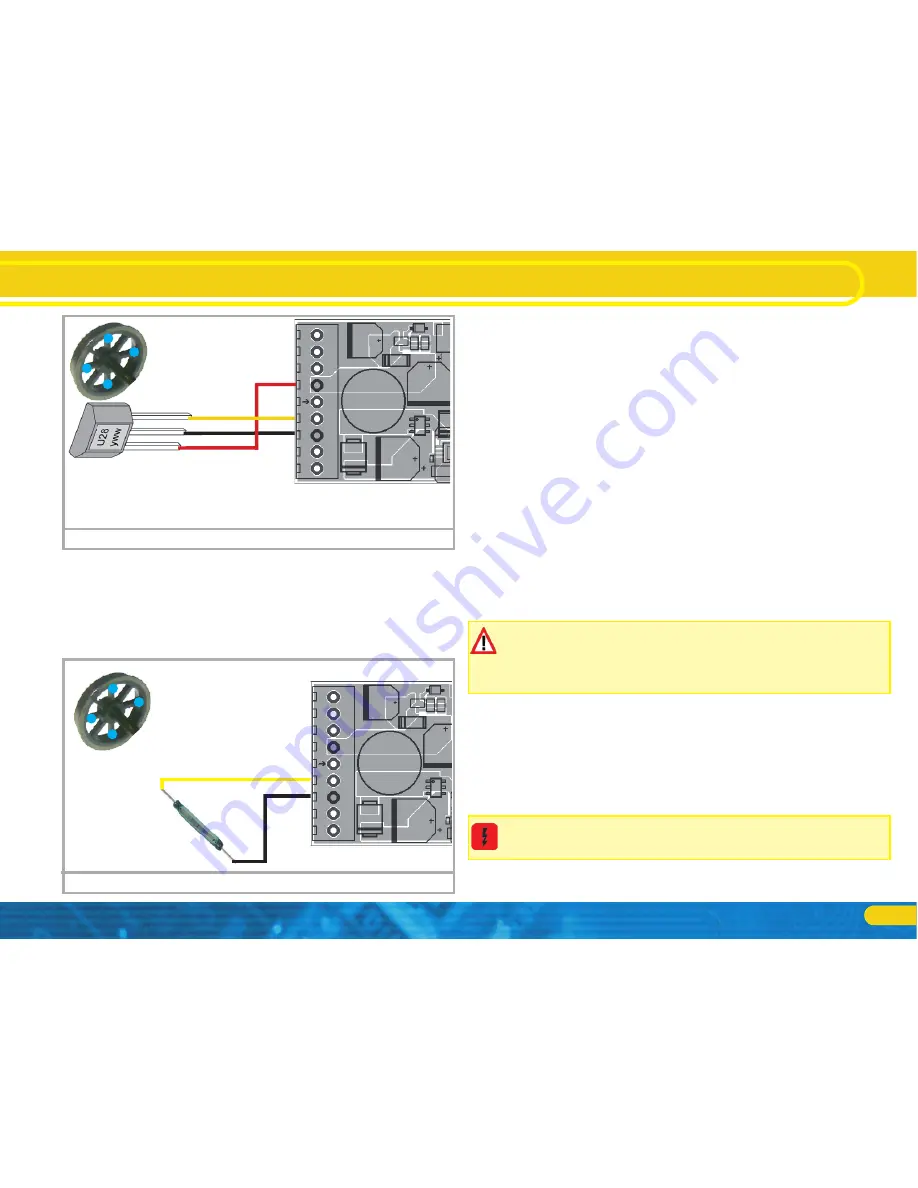
Place four miniature magnets on the inner side of the driving
wheel in such a way that the magnet will trigger the HALL IC each
time it will pass the sensor IC. For 3-cylinder locomotives, you may
even need 6 magnets, depending on the cylinder configuration.
6.9.7.2. Reed switch sensor
If you have trouble obtaining a hall sensor IC, you may also use a
subminiature reed switch. They are connected to the decoder with
two pins only. However, their sensitivity is not as good as hall IC
sensors and stronger magnets may be needed in order to trigger
these reed switches correctly. Furthermore the position of the reed
switches needs to be considered.
6.10. Connecting Capacitors
On many older layouts, current pick up of locomotives is not very
reliable. Therefore, power interruptions may cause a stop or jerky
movement when the locomotive travels over turnouts at low
speeds. This can be overcome with buffer capacitors (100 mF /
25V or higher show the desired results). If desired you may con-
nect them to the LokPilot V4.0 or LokPilot micro V4.0.
Soldering wires onto a decoder requires quality soldering equip-
ment and experience. Our warranty does not cover damage
caused by inappropriate soldering. Consider carefully if you re-
ally need that capacitor.
6.10.1. LokPilot H0, LokPilot micro decoders
You can connect two larger capacitors as per the circuit in the
upper half of figure 21.
The capacitor is charged via a resistor (100 Ohms) thus preventing
the digital system from interpreting the charging current as short
circuit at the time of switch-on. The diode makes sure that the
energy of the capacitor is fully available when required.
However, you may not run the LokPilot decoder on AC layouts
anymore. Risk of destruction!
Input
GND
VCC
Hall Sensor IC
4x
Mini
magnet
HALL IC wiring to a LokPilot XL
Figure 19:
Input
GND
Reed switch
4x
Mini
magnet
Reed switch wiring to a LokPilot XL
Figure 20:
Summary of Contents for LokPilot Fx V4.0
Page 74: ...74 Notes ...


