42
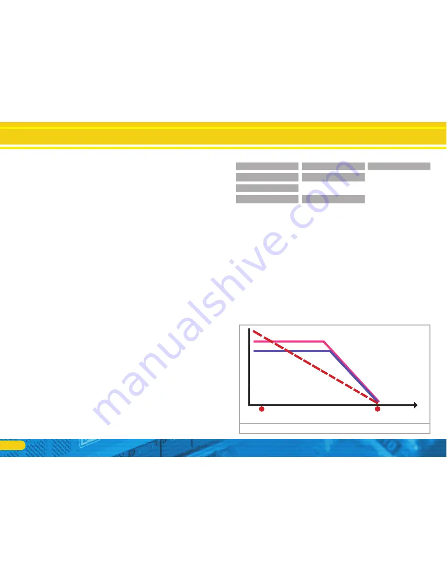
10.6. Constant brake distance
LokPilot V4.0
LokPilot V4.0 DCC LokPilot V4.0 M4
LokPilot micro V4.0
LokPilot micro V4.0 DCC
LokPilot XL V4.0
An attractive function hides behind CV 254 (ESU brake mode):
Here you can set a constant distance for braking the train, from
the beginning of the brake sector to the stopping point. Thus, it
is possible to stop the train right in front of a red signal regardless
of the speed. The LokPilot simply calculates the required brake
effect.
The higher the value in CV 254, the longer is the brake distance.
Simply make some trials on a test track in order to find the values
best suited to your locomotive.
If CV 254 is set to 0, then the normal time mode according to
chapter 10.1. will automatically turn on.
The constant brake distance is only active in brake sectors. When
you turn the throttle back to 0, the locomotive will slow down as
per the value in CV 4.
Adapting the Driving Characteristics
Constant brake distance
Figure 24:
Train A) slows down linearly: Immediately after reaching the brak-
ing point, it slows down linearly and stops at the stop point.
Speed
Entry in the brake sector
Desired stop point
(defined by CV 254)
Train B) is fast, continues to drive
only a short distance to the defined
braking point, slows down and stops
at the braking point.
Train C) also
continues to travel to
the defined braking
point, slows down
and stops at the
same point.
Way
As a new function the LokPilot V4.0 decoder supports the ABC
braking technique introduced by Lenz®. In order to use this func-
tion a group of anti-parallel diods will be be soldered to one half
of the track. The resulting fall of voltage generates an assymetrical
DCC signal. LokPilot decoders are able to detect the potential dif-
ference between the left and right half of the signal. If desired, the
decoder will be stopped.
To be able to use the ABC technique you also need, beside the ad-
equate LokPilot V4.0 decoder, an appropriate brake module. The
ABC technique can only be operated with boosters offering an
exact symmetrical output. All command stations and boosters by
ESU and Lenz® garantuee a symmetrical output. We don´t recom-
mend to use other boosters for the ABC technique.
If you wish to stop the LokPilot decoder when the track signal is
•
stronger on the right side than on the left side (and the diods are
also installed on the left side), set bit 2 in CV 27.
If you wish to stop the LokPilot decoder when the track signal is
•
stronger on the left side than on the right side (and the diods are
also installed on the right side), set bit 1 in CV 27.
If you want to stopp the decoder no matter in which half of the
•
track the diods are set, please set bit 2 and bit 1 in CV 27 (CV
27 = 3).
10.5.4.1. ABC “slow approach” section
The decoders also detect ”slow approach” sectors implemented
with the Lenz® BM2 module. The desired speed in the slow ap-
proach sector can be adjusted with CV 123. The value 255 cor-
responds with full speed while the value 0 would stop the loco-
motive.
10.5.4.2. ABC detection threshold
In some operational situations it may happen that the LokPilot
decoder does not detect the ABC braking section. This may be
caused by the wiring or the boosters respectively the braking di-
odes.
You can influence the detection sensitivity with the aid of CV
134. Change the default value (12) step by step and test until you
achieve the desired result.
Summary of Contents for LokPilot Fx V4.0
Page 74: ...74 Notes ...


