10
Wiring the outputs
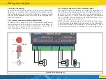
5.4.3. Daylight signals with LEDs, common cathode
For some daylight signals (especially those by Viessmann®) the
minus poles („Cathode”) of the individual LEDs are connected.
These must be wired to a negative potential („GND”). The plus
pole of the single LEDs („Anode”) is connected to the respective
output, as shown in Fig. 4 for output 1 and 2. Here, too, it is
essential to use resistors.
The corresponding output must be configured as a „pull” stage
on the software side, otherwise the LEDs will not light up.
5.4.4. Motorised turnout drives
Thanks to the push-pull stages of all outputs, the SignalPilot can
be used to operate motorized turnout drives without further mea-
sures. Motorised turnout drives have a small, geared motor, the
direction of which can be reversed by reversing the motor voltage.
Often, limit switches are installed to prevent the motor from bur-
ning through when it has arrived at the end position.
If the direction of rotation is incorrect, simply swap the two out-
puts on the SignalPilot.
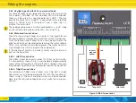
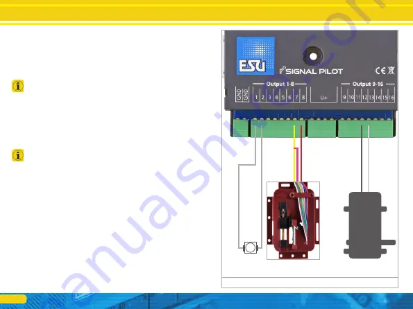
5.4.4.1. LGB® Turnout drive
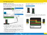
The LGB® turnout drive part number 12010 has no limit switch.
It is connected as shown in Fig. 5 and should be programmed by
means of the software for turning it off after 2 seconds, thus avoi-
ding overheating of the drive and excessive load on the SignalPilot.
5.4.4.2. Tillig® turnout drive
The well-known Tillig® turnout drives (e.g.: Tillig 86112 under-
floor drive) can also be operated directly with the SignalPilot as
shown in Fig. 5. The pink and yellow wires must be connected.
Here, too, the software configuration must match the wiring con-
nection.
M
Figure 5: LGB® Turnout drive
LGB 12010
Tillig 86112
connect
pink and
yellow
red
DC Motor


