background image

19

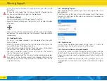
Each signal always shows exactly one signal image until a different 

signal image is to be shown. The SignalPilot saves the current si-

gnal image permanently, so that even after a power failure or on 

the next operating day, the last signal image shown is automati-

cally displayed again.

Example 2 also shows that not all combinations need to be used. 

No signal image is assigned to the „button” turnout number 8 

„red/odd”; therefor nothing will happen if this button is pressed.

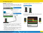
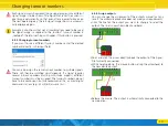
6.8.3. Changing turnout numbers

If you want to use a different turnout number, enter the desired 

number(s) directly in the input field.

You can also assign the same turnout number to multiple signals. 

These will then be switched simultaneously. If a signal requires 

several turnout numbers (starting with three aspects), different 

turnout numbers must be assigned. The turnout numbers do not 

have to be continuous, but we recommend this, as most digital 

command stations (e.g.: ESU ECoS) assume this.

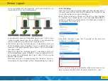
6.8.4. Assign outputs

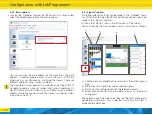
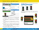
You can change the assignment of the outputs manually at any 

time if the automatic procedure does not meet your requirements.

• Click the line for the output you want to change to select the 

output. The line is now shown black and bold.

• Point and click the arrow directly above the output of the Signal-

Pilot currently connected.

• While holding down the mouse button, drag the arrowhead to 

the new desired output.

•  Release the mouse. The output is automatically connected to the 

new position.

Changing turnout numbers

Summary of Contents for SignalPilot 51840

Page 1: ...Instruction manual 1 Edition January 2021 P N 00321 24476 From decoder firmware 1 0 4 51840 SignalPilot SignalPilot ...

Page 2: ...6 6 8 Configuring Signals 16 Content 6 8 1 Signal name 16 6 8 2 Turnout numbers and signal aspects 16 6 8 3 Changing turnout numbers 19 6 8 4 Assign outputs 19 6 8 5 Switch all outputs to GND 20 6 9 Configuring outputs 20 6 9 1 Switch output to GND 21 6 9 2 Lighting effects 21 6 9 3 Fade in and fade out times 21 6 9 4 Delay times 21 6 9 5 Assign SPE relays 22 6 9 6 Use alternative output configura...
Page 3: ...der Firma Gebr Märklin und Cie GmbH Göppingen RailCom ist ein eingetragenes Warenzeichen der Firma Lenz Elektronik GmbH Gießen Alle anderen Warenzeichen sind Eigentum ihrer jeweiligen Rechteinhaber ESU electronic solutions ulm GmbH Co KG entwickelt entsprechend seiner Politik die Produkte ständig weiter ESU behält sich deshalb das Recht vor ohne vorherige Ankündigung an jedem der in der Dokumentat...

Page 4: ...ment may destroy it 1 Declaration of Conformity The manufacturer ESU electronic solutions ulm GmbH Co KG Edisonallee 29 D 89231 Neu Ulm hereby declares under its sole responsibility that the product Product name SignalPilot Type 51840 complies with all relevant provisions of the Electromagnetic Com patibility Directive 2004 108 EC The following harmonised stan dards have been applied EN 55014 1 20...

Page 5: ...spect signals are conceivable Depending on the number of out puts involved one or more turnout numbers accessory addresses are assigned to each signal with the help of which you can later switch the individual signal aspects Up to 16 turnout numbers are available for this purpose The configuration of the signal aspects is carried out exclusively with the aid of the ESU LokProgrammer software You s...
Page 6: ...48 Märklin Motorola Turnout numbers 1 256 Up to 16 turnout numbers SANs for signal aspects Separate turnout number for global blanking Separate turnout number address for POM programming Configuration With ESU LokProgrammer and LokProgrammer software Dimensions 86mm x 86mm x 25mm 4 3 Scope of delivery The SignalPilot is supplied with 5 removable terminal blocks 1x 4 pole for the track connection 2...
Page 7: ... be taken from the command station or booster c Connect the Terminals Trk A and Trk B to the track output of the command station or boosters from which the SignalPilot should receive its commands d Terminals U The return wire of the connected accessories lamps LEDs solenoids etc can be connected to these ter minals The voltage is equal to the supply voltage i e track voltage e Terminals GND Altern...

Page 8: ...rnal power supply For larger layouts with many electric loads we recommend the use of an external power supply DC and AC power supplies are sui table with the specifications specified in chapter 4 2 We recom mend the use of a stabilized DC power supply with at least 18V DC and at least 3A output power e g ESU part number 50119 This type of connection cannot be used for programming on the programmi...

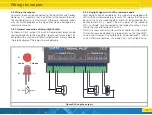
Page 9: ...ys observe the rated voltage of the lamps to avoid damage 5 4 2 Daylight signals with LEDs common anode Most daylight signals available on the market are equipped with LEDs with common anode e g Busch This means that the ano des of all LEDs are wired together and must be connected to a positive potential pole The minus poles of the individual LEDs cathode are connected to the respective output Fig...

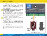
Page 10: ...e direction of which can be reversed by reversing the motor voltage Often limit switches are installed to prevent the motor from bur ning through when it has arrived at the end position If the direction of rotation is incorrect simply swap the two out puts on the SignalPilot 5 4 4 1 LGB Turnout drive The LGB turnout drive part number 12010 has no limit switch It is connected as shown in Fig 5 and ...

Page 11: ...e SwitchPilot Extension module are supplied by the SignalPilot 5 5 1 Relay outputs Fig 6 shows the connections a The outputs 1 to 4 indicate one each of two relay outputs namely A and B which are switched together 2 x changeover bistable The software configuration determines when the re spective relay output is switched b Terminals for ground and U rectified track voltage supplied by the SignalPil...

Page 12: ...r adapter to learn more about the system requirements of the ABC braking technique Connecting the SwitchPilot Extension Figure 8 Switch the ABC braking section with SignalPilot and SwitchPilot Extension 2 Leitergleis 2 rail track 0 B 3 conductor track AC 2 conductor track DC Center conductor separation Center conductor separation Main track Holding section Direction of travel Main track 51808 5180...

Page 13: ...the SwitchPilot tab Configuration with LokProgrammer 6 Configuration with LokProgrammer The SignalPilot must be configured with the LokProgrammer and the appropriate software Although all settings would also be ac cessible via CV programming this procedure is not recommended or documented due to its complexity 6 1 Procedure A new SignalPilot should first be configured with the aid of the LokProgra...

Page 14: ...ulation method Here the turnout numbers can devi ate by the value of 4 6 4 Signals register No further relevant settings can be made in the Decoder regis ter All settings for the SignalPilot and the connected signals are made in the Signals register Click on the Signals icon in the left column of the screen You will now see the main window which is structured as follows a Choice menu for predefine...

Page 15: ... the latest The Minimum pause determines the minimum time that must elapse before a light that has been turned off is switched on again The Maximum pause determines the maximum time after which the light is switched on again Within these parameters the SignalPilot determines when lights are switched on and off and how long they are on or off If the minimum and maximum pause times are set to the sa...

Page 16: ...nsultation The connec tions to the outputs are deleted All settings programmed for this signal will be irretrievably deleted Any gaps in the function outputs are ignored when automa tically assigning further function outputs However they can be assigned manually Moving Signals 6 8 Configuring Signals The properties of each placed signal can be changed after it has been selected Click the name of t...

Page 17: ... and Hp1 for Proceed One turnout number is suf ficient to represent these two signal aspects The following figure contains all the information a The signal aspect Hp0 is shown when the assigned turnout number here 5 indicates the state r i e Red Odd b The signal image Hp1 is displayed when the assigned turn out number here 5 indicates the state g i e Green Straight c The figure 1 indicates that th...

Page 18: ...nal uses the first two out of a total of 16 turnout numbers of the SignalPilot The turnout numbers used for signals are internally referred to as SAN Signal Address Number e The currently assigned turnout numbers here 7 and 8 are displayed in square brackets after the signal name c If you hover the mouse on one of the signal images you will see which lights will be on To switch the two signal aspe...
Page 19: ...number to multiple signals These will then be switched simultaneously If a signal requires several turnout numbers starting with three aspects different turnout numbers must be assigned The turnout numbers do not have to be continuous but we recommend this as most digital command stations e g ESU ECoS assume this 6 8 4 Assign outputs You can change the assignment of the outputs manually at any tim...

Page 20: ...4 3 Although the return wires are not displayed in the software they must nevertheless not be forgotten 6 9 Configuring outputs The properties of all outputs used in a signal can be customised Thus for instance the brightness of the LEDs as well as flash and fade effects can be adjusted The conditions that cause the output to be switched cannot be changed in this way The logic of the signal i e ho...

Page 21: ...t Light Simulates the typical flickering of fluorescent lamps Single Strobe Random Like Single Strobe but the exact time of the flash is randomly chosen Defective Fluorescent Light A defective fluorescent lamp that ne ver turns on Motorised Turnout Effect for motorised turnout drives The revs of the motor can be reduced if it turns too fast 6 9 3 Fade in and fade out times Every light can be faded...

Page 22: ... nals where individual lights e g green light of the DB KS signal can either light up continuously or flash depending on which other signal lights are still turned on In these cases the SignalPilot can switch over to the alternative configuration You cannot define which signal aspect uses the basic or alternative output configuration with the LokProgrammer software This is set when defining the si...

Page 23: ...n use the integral Virtual Cab of the LokProgrammer software 6 13 1 Virtual Cab The virtual cab of the LokProgrammer software can also be used for testing signal aspects provided that the power consumption does not exceed the capability of the LokProgrammer This should not be a problem for daylight signals For testing the connection to the LokProgrammer must be made as shown in Fig 5 2 Select the ...

Page 24: ...ht for Hp2 On the virtual cab these would be the buttons 7 A for Hp0 7 B for Hp1 8 B for the yellow light for Hp2 6 14 Distant signals at the same mast of a main signal A particular challenge are combinations of distant signals and main signals on a common mast in block control operation Here the distant signal displays the aspect of the following main signal For this to work two conditions must b...

Page 25: ...with the SignalPilot Let s have a look at an ex ample of how this can be accomplished In our example there are three block signals each with its own turnout number namely one two and three In our example the wiring is irrelevant only the turnout numbers count The distant signal for the block signal 2 is mounted on the mast of the first block signal Therefore it also is assigned the turnout number ...

Page 26: ...nted on the same mast and en ter the corresponding SAN in the External box Now all signals should work correctly Please also observe the fol lowing notes The blanking of the distant signal can also respond to several SANs This is important if in addition to Hp0 another signal as pect can be displayed on the main signal e g Hp00 As soon as you enter a SAN another selection box for the next SAN will...

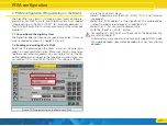
Page 27: ...ke sure that you have selec ted the correct accessory address You can write all CVs of the Sig nalPilot decoder and subject to the type of command station you can read out CVs as well With the ECoS this is done as follows Figure 10 Programming on the Main with ECoS Go to the ECoS main menu Select Programming on the Main POM DCC and Accesso ry decoder Select the POM address of the SignalPilot The c...

Page 28: ...w to do this in the manuals of the command station respectively the throttle If the decoder has understood the address it acknowledges this by lighting the LED continuously for about 1 second The SignalPilot then switches to normal operating mode and the LED is extinguished 10 RailCom RailCom is a technique for transferring information from the de coder back to the command station When RailCom is ...

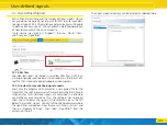
Page 29: ...a in the format of a text file that is readable by both people and computers 12 2 Directory for user defined signal aspects Every time the program starts or creates a new project file for the SignalPilot the LokProgrammer software checks whether XML de scription files for customised signals are contained in a directory you define on your hard drive If so the software tries to import them and will ...

Page 30: ...able to us either in our support forum or to contact us by e mail We also provide a telephone hotline which should only be used in the case of really special requests For Germany by phone 49 0 731 1 84 78 106 Tuesday Wednesday from 10 00 to 12 00 o clock by Fax 49 0 731 1 84 78 299 by E Mail www esu eu kontakt by mail ESU GmbH Co KG Edisonallee 29 D 89231 Neu Ulm www esu eu For USA Canada Australi...

Page 31: ...the enclosed failure report card as detailed and precise as possible and return it with your faulty product Please use the appropriate postage when shipping to ESU Extend of warranty exclusions This warranty covers free of charge repair or replacement of the faulty part provided the failure is demonstrably due to faulty design manu facturing material or transport Any further claims are explicitly ...

Page 32: ...2 Error Transistor outputs Short circuit Servo outputs No function from the start No Function Programming on the Main 3 Error description 4 Receipt Please enclose your receipt invoice Otherwise no warranty possible 5 Additional information 6 Your retailer Retailer s stamp or address Trouble shooting sheet ...

Reviews: