22
6.9.5. Assign SPE relays
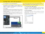
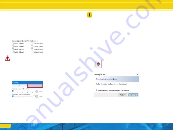
Each active output can control one of the four relays of a connec-
ted SwitchPilot Extension module, if required. This may be useful
for activating a braking sector or the polarisation of a turnout frog
(see chapter 5.5). Select the relay(s) as well as its status (i.e.: which
contacts should be active) when the corresponding output is tur-
ned on. Each relay can be set to position I (normally closed con-
tact) or position II (normally open contact) and retains its position
(status) until it is switched to the other status.
Make sure that the assignments make sense. Assuming that two
outputs are active at the same time, the settings for the relay must
not contradict each other.
6.9.6. Use alternative output configuration
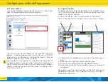
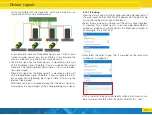
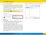
In addition to its basic configuration „1”, each function output
also has an alternative output configuration „2”. You can change
the display by clicking on the corresponding digit in the detail area
to change the alternative output configuration.
The alternative output configuration is used, for example, for sig-
nals where individual lights (e.g.: green light of the DB KS signal)
can either light up continuously or flash, depending on which
other signal lights are still turned on. In these cases, the SignalPilot
can switch over to the alternative configuration.
You cannot define which signal aspect uses the basic or alternative
output configuration with the LokProgrammer software. This is set
when defining the signal aspect.
6.10. Save the project file to the hard drive
If you have placed all signals as desired and completed all set-
tings, you should save the project file to the hard drive, so that it is
available for later changes.
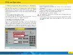
• Select the command „Save under...” in the „File” menu and as-
sign a meaningful name to the project file.
6.11. Write settings to the SignalPilot
The next step is to transfer the settings to the SignalPilot. Make
sure that the connection is exactly as shown in chapter 6.2.
• Select the command „Write decoder data...” in the „Program-
mer” menu or click on the icon in the toolbar.
• Then select „Next” in the dialog box.
The decoder data are transmitted to the SignalPilot. If you receive
an error message, check the connection and unplug the Switch-
Pilot extension module for programming.
The SignalPilot is now ready for wiring.
Assign SPE relays
Wiring the SignalPilot


