25
ELECTRICAL INTERCONNECTION
INSTALLATION INSTRUCTIONS
2
BEFORE CONNECTING
For the professional installation of a sound system, car audio retail stores offers appropriate wire kits. Ensure a sufficient profile section
(at least 25 mm
2
), the suitable fuse rating and the conductivity of the cables when you purchase your wiring kit. Clean and remove rust-
streaked and oxidized areas on the contact points of the battery and the ground connection. Make sure that all screws are fixed tight after
the installation, because loose connections cause malfunctions, insufficient power supply or interferences.
FUSE
The fuses, which protect the device against short circuits and overload, are located inside the device. To replace a defective fuse, first
clamp off the device from the power supply. Then remove the bottom plate of the device and replace the defective fuse in the inner slot
with a new fuse of the same type and same rating.
REM
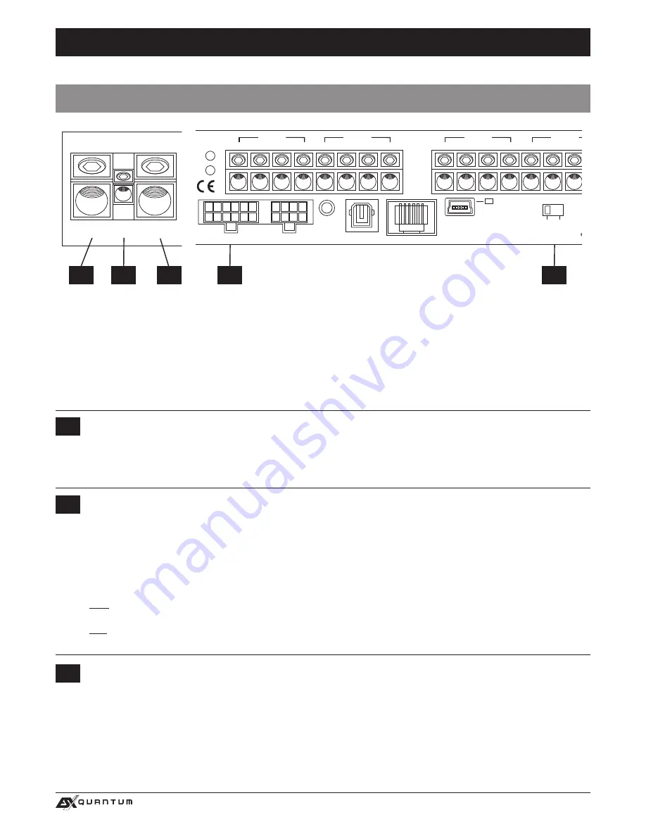
Connect the turn-on signal (e.g. automatic antenna) or the turn-on remote signal of your head unit with the REM-terminal of the
amplifier. Use therefor a suitable cable with a sufficient cross section (0,5 mm
2
). Hereby the amplifier turns on or off with your
head unit.
AUTO TURN ON
If you operate the amplifier with the
HIGH LEVEL INPUT (A)
, you must not connect the REM cable of the device. Set the
AUTO
TURN ON (B)
switch to position ON. The amplifier detects now by a so called ”DC Offset” (a voltage increase up to 6 volts) on
the high level speaker outputs. Then, if the head unit is turned on the amplifier turns automatically on. As soon as the head unit
is turned off, the amplifier shuts down automatically.
Note:
The
AUTO TURN ON
usually works with 90% of all head units, because they are equipped with the ”High Power” outputs.
Only with a few older head units the
AUTO TURN ON
function is not applicable.
Hint:
If you use the
AUTO TURN ON
function, a +12V remote turn-on signal is routed to the
REM
socket, which you can use for
turning on other devices. Simply connect the two REM sockets of the devices with each other.
3
BATT+12V
Connect the BATT+12V-terminal with the +12V pole of the vehicle’s battery. Use a suitable cable with a sufficient cross section
(at least 25 mm
2
) and install an additional in-line fuse. For safety reasons the distance between the fuse block and the battery
should be shorter than 30 cm. Do not set in the fuse into the fuse block until the installation is accomplished.
1
GND
Connect this GROUND terminal with a suitable contact ground point on the vehicle’s chassis. The ground wire must be as short
as possible and must be connected to a blank metallic point at the vehicle’s chassis. Ensure that this ground point has a stable
and safe electric connection to the negative “–”pole of the battery. Check this ground wire from the battery to the ground point
if possible and enforce it, if required. Use a ground wire with a sufficient cross section (at least 25 mm
2
) and the same size like
the plus (+12V) power supply wire.
1
2
A
B
3
+12V
GND
REM
POWER INPUT
LINE INPUT
LINE OUTPUT
AUX IN
POW.
PRT.
PC CONNECT
USB
FL
FR
RL
RR
SUB L
SUB R
FL
FR
RL
RR
SUB L
SUB R
H
+
–
+
–
G F E
WiFi BOX
OPTICAL INPUT
REMOTE
HIGH LEVEL INPUT
ONLY WITH HIGH LEVEL INPUT
AUTO TURN ON
OFF ON
BRIDGED
D
+
–
C
+
–
BRIDGED
B
+
–
A
+
–
LINE INPUT
AUX IN
PC CONNECT
USB
WiFi BOX
OPTICAL INPUT
REMOTE
HIGH LEVEL INPUT
ONLY WITH HIGH LEVEL INPUT
AUTO TURN ON
OFF ON
+12V
GND
REM
POWER INPUT
POW.
PRT.
LINE OUTPUT
H
G
BRIDGED
D
+
–
C
+
–
BRIDGED
B
+
–
A
+
–
BRIDGED
F
+
–
E
+
–
+12V
GND
REM
POWER INPUT
LINE INPUT
AUX IN
PC CONNECT
USB
WiFi BOX
OPTICAL INPUT
REMOTE
HIGH LEVEL INPUT
ONLY WITH HIGH LEVEL INPUT
AUTO TURN ON
OFF ON
POW.
PRT.
BRIDGED
D
+
–
C
+
–
BRIDGED
B
+
–
A
+
–
BRIDGED
F
+
–
E
+
–
BRIDGED
H
+
–
G
+
–
QE80.4 DSP
QE80.6 DSP
QE80.8 DSP
+12V
GND
REM
POWER INPUT
LINE INPUT
LINE OUTPUT
AUX IN
POW.
PRT.
PC CONNECT
USB
FL
FR
RL
RR
SUB L
SUB R
FL
FR
RL
RR
SUB L
SUB R
H
+
–
+
–
G F E
WiFi BOX
OPTICAL INPUT
REMOTE
HIGH LEVEL INPUT
ONLY WITH HIGH LEVEL INPUT
AUTO TURN ON
OFF ON
BRIDGED
D
+
–
C
+
–
BRIDGED
B
+
–
A
+
–
LINE INPUT
AUX IN
PC CONNECT
USB
WiFi BOX
OPTICAL INPUT
REMOTE
HIGH LEVEL INPUT
ONLY WITH HIGH LEVEL INPUT
AUTO TURN ON
OFF ON
+12V
GND
REM
POWER INPUT
POW.
PRT.
LINE OUTPUT
H
G
BRIDGED
D
+
–
C
+
–
BRIDGED
B
+
–
A
+
–
BRIDGED
F
+
–
E
+
–
+12V
GND
REM
POWER INPUT
LINE INPUT
AUX IN
PC CONNECT
USB
WiFi BOX
OPTICAL INPUT
REMOTE
HIGH LEVEL INPUT
ONLY WITH HIGH LEVEL INPUT
AUTO TURN ON
OFF ON
POW.
PRT.
BRIDGED
D
+
–
C
+
–
BRIDGED
B
+
–
A
+
–
BRIDGED
F
+
–
E
+
–
BRIDGED
H
+
–
G
+
–
QE80.4 DSP
QE80.6 DSP
QE80.8 DSP
Summary of Contents for Quantum QE80.8DSP
Page 21: ...21 NOTITZEN ...
Page 41: ...41 NOTES ...
Page 42: ...42 NOTES ...
Page 43: ...43 NOTES ...


