31
FUNCTIONAL INSTRUCTIONS
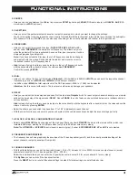
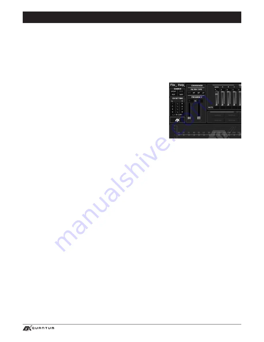
2. SOURCE
:
• Here you can choose between the different input sources
SPDIF
(optical input),
MAIN
(RCA audio inputs) or
HI LEVEL
,
AUX
(RCA
stereo input) and
WiFi
(optional).
3. CH-SETTING
:
• Here you select the particular output channels or output channel pairs in which you want to change the settings.
You have the option to link the respective channel pairs for
L
and
R
with the lock symbol in the middle to synchronize the settings for
both channels. With
L-> R COPY
you can also copy the setting of the currently selected left channel to the right channel.
4. CROSSOVER
:
• Here you can select the required filter type (
FILTER TYPE OFF
,
HP
,
BP
or
LP
)
and set under
FREQUENCY
the desired cut-off frequency. The sliders only work
when the particular filter type is activated. As soon a filter type is selected, it will be
displayed graphically under point 8.
Note:
If you have selected a filter type, the cut-off frequency can also be changed
under point 8 with the mouse. Click and hold the red dot and move the cursor to
the desired location on the frequency band.
• Hint:
Instead of using the slider, you can also type in the cut-off frequency directly
with the keyboard after a double click on the values below
FREQUENCY
.
Confirm by pressing
ENTER
.
5. GAIN
:
• Here you can reduce the level of the individual
Outputs A – H
from 0dB to -40dB. With
MUTE
you can mute the respective channel.
If necessary, you can use
MUTE
under
MAIN
to mute all output channels.
• In addition, under
MAIN
, the total output level of the DSP processor (-40dB to + 12dB) can be adjusted.
Attention:
Use this control with caution. Too loud level could seriously damage your speakers.
6. DELAY
:
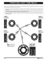
• Here you can adjust the time delay and phase shift of the individual
Outputs A – H
. For each output channel channel you can individ-
ually set the time delay of the signal under
DELAY
. Above
PHASE
, the unit of delay can be switched between ms (milliseconds) and
cm (centimeters).
Hint:
Instead of using the slider, you can also type in the value directly with the keyboard after a double click on the values above the
sliders. Confirm by pressing
ENTER
.
• Below the sliders you can switch the phase from 0° to 180 ° individually for each channel.
• With these two functions you can match your sound system to the vehicle acoustics and adjust the acoustic stage perfectly.
7. HP SLOPE / LP SLOPE - CONFIGURATION OF SLOPE
:
• Select under
HP/SLOPE
the desired slope of the high-pass filter and under
LP/SLOPE
the slope of the low-pass filter, which is se-
lectable in 6dB steps, starting from 6 dB per octave (very flat) to 48 dB per octave (very steep).
Note:
The
HP/SLOPE
or
LP/SLOPE
control panel is inactive (gray), if under
4. CROSSOVER
HP
,
LP
and
BP
is not selected.
8. FREQUENCY BAND PREVIEW
:
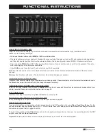
• The frequency band shows graphically the envelope of the 31-band equalizer (point 9) and the currently selected settings of the
output channel or output channel pair from point 4.
9. 31-BAND EQUALIZER
:
• With the sliders below you can set the desired dB value (-18 to +12) between 20 Hz to 20000 Hz for each output channel (except
subwoofer channels G & H: 11-band equalizer 20 Hz - 200 Hz).
Below the individual sliders you can enter the Q (quality) as numeric value (0.5 for very shallow to 9 for very steep).
With
ByPass
you can switch off the Equalizer function.
Press the
RESET
button to reset all Equalizer settings to default (All other settings are not affected by this).
Summary of Contents for Quantum QE80.8DSP
Page 21: ...21 NOTITZEN ...
Page 41: ...41 NOTES ...
Page 42: ...42 NOTES ...
Page 43: ...43 NOTES ...


