


12
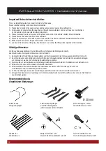
INSTALLATION NOTES / Installationshinweise
Einbautipps:
Installation hints:
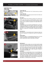
GPS antenna:
The GPS (12) antenna must be mounted horizontally in front on the dashboard
(ensure a clear view to the sky). A metalized windscreen allows no recepti-
on. If a factory GPS antenna with the same connector type (Fakra) is already
available, it can be used. Then the installation of the included GPS antenna is
not necessary.
GPS Antenne:
Die GPS Antenne (12) muss waagerecht, nach Möglichkeit vorne auf dem Ar-
maturenbrett montiert werden (auf freie Sicht zum Himmel achten). Bei einer
metallbedampften Scheibe ist kein Empfang möglich. Falls eine werksseitige
GPS-Antenne mit dem denselben Steckertyp (Fakra) bereits vorhanden ist,
kann diese verwendet werden. Die Installation der beiliegenden GPS Antenne
entfällt.
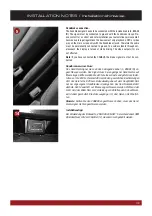
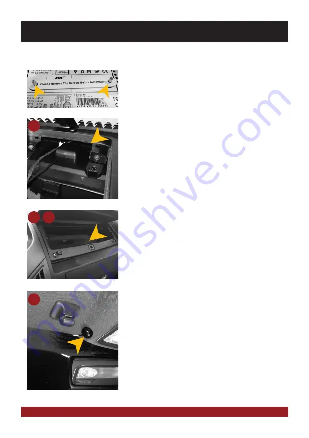
BT-Microphone:
The device has an internal microphone. For an even better transmission quality
you can mount the supplied microphone (8) at a suitable point such as at the
A-pillar (driver‘s side) or on the roof lining at the interior lamp. Avoid laying the
cable over the steering column. In general, the cable should be long enough to
reach a desired mounting point at the A-pillar (driver‘s side) while laying the
cable over the the passenger‘s side. A possibly existing factory microphone is
not compatible with the ESX device.
BT-Mikrofon:
Das Gerät besitzt ein internes Mikrofon. Für eine noch bessere Übertragungs-
qualität können Sie das beiliegende Mikrofon (8) an einem geeigneten Mon-
tagepunkt wie z.B. an der A-Säule (Fahrerseite) oder am Dachhimmel bei der
Innenraumleuchte anbringen. Vermeiden Sie das Verlegen des Kabels über
die Lenksäule. In der Regel sollte das Kabel lang genug sein, um die A-Säule
(Fahrerseite) über die Beifahrerseite zu erreichen. Ein evtl. werksseitig vorhan-
denes Mikrofon ist nicht kompatibel mit dem ESX Gerät.
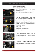
USB Connectors:
Route the cables (11) to a desired location, such as the glove box. If necessary,
you must drill openings. One of the USB ports is needed for the TMC antenna
(13).
USB-Anschlüsse:
Verlegen Sie die Kabel (11) an den gewünschten Einbauort, wie z.B. im Hand-
schuhfach. Gegebenenfalls müssen dafür Öffnungen gebohrt werden.
Einer der USB Anschlüsse wird für die TMC Antenne (13) benötigt.
12
11 13
8
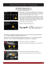
Transportation lock:
Remove both transportation locks on top of the device before you start the
installation.
Transportsicherung:
Entfernen Sie beide Transportsicherungen auf der Oberseite des Geräts, bevor
Sie mit der Installation beginnen.


