background image

2

10

Before you start with the installion, 

. Keep this Operation Manual for later use.

TRAFFIC

Please read this Operation Manual 

carefully

The Driver should never operate these products while the vehicle is in motion! 

Installation of all TV monitors must be out of the driver`s field of vision.

BUILD-IN POSITION

Installation of all TV monitors must be out of the driver`s field of vision. This product 

should never be placed near or over an heat vent. Make sure to keep products away 

from direct sunlight at the build in position. Do not mount the product where it will 

obstruct the deployement of the airbag or  in an area where it would affect the 

vehicular control. Also be careful to avoid mounting the product, where it can become

hazardous during sudden stops or in the event of an accident.

INSTALLATION 

Quality installations are best performed by qualified and certified installers.

CLEANING THE SCREEN

Use only a damp cloth to clean the screen and use only purified water on the cloth 

wiring out all excess water prior to wiping the screen. Do not use any cleaners or 

chemicals to clean the screen. In most cases a dry cloth will do!

LIQUIDS

If there is any liquid on these products, pull your vehicle to the roadside and turn-the 

key off to disconnect or wipe the products with a towel. Do not operate the equipment 

until all liquids have either evaporated or you have the monitor was inspected at the 

service center by a qualified technician.

WATCHING THE MONITOR WITHOUT ENGINE RUNNING

Watching the Monitor for an extended period of time without engine running may 

deplete the vehicle`s battery charge.

Safety Advice

Summary of Contents for VM701S

Page 1: ...7 17 8 cm TFT LCD 16 9 Car Monitor Bedienungsanleitung Owner s Manual...

Page 2: ...iodesign de french Inhaltsverzeichnis Technische Daten 7 17 8 cm TFT LCD 16 9 Auto Monitor Installation freistehend oder in Kopfst tze Aufl sung 1400 x 234 px Aufl sung RGB 480 x 234 px Kontrast Verh...

Page 3: ...iert werden dass es im Falle eines Unfalls nicht zur Gefahr wird INSTALLATION Die besten Einbauten werden von qualifiziertem Fachpersonal oder geschulten Technikern durchgef hrt REINIGUNG Benutzen Sie...

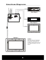
Page 4: ...itte achten Sie beim Anschlie en der einzelnen Komponenten auf korrekte Polung der Kabel bzw auf die richtigen Kennfarben der Cinch Stecker Rot Z ndung Monitor 1 Stecker mit Kabelsatz Gelb Batterie 12...

Page 5: ...re Bauteile des Fahrzeugs besch digen D Methode 2 Installation in der Nackenst tze Schneiden Sie dann eine aus reichende Einbau ffnung B in die Nackenst tze Als Vorlage kann das innere Ma des Einbaura...

Page 6: ...uschalter 2 Bild spiegeln oder drehen 3 Aktiviert das OSD Men 4 Stummschaltung 5 Taste schaltet zwischen Audio Video Signal 1 oder 2 6 Lautst rke 7 Helligkeit 8 Farbe 9 Kontrast Basis Funktionen 1 2 1...

Page 7: ...ng dreimal um zu den Einstellungen f r Farbe Color zu gelangen Danach dr cken Sie die LINKS oder RECHTS Taste auf dem Display oder die HOCH oder RUNTER Taste auf der Fernbedienung um die gew nschte Ei...

Page 8: ...lit t 2 Erh hen Sie das Helligkeits Kontrastverh ltnis 1 1 Kein Farb Bild vom Video Player 2 Das Anschlusskabel des Monitors hat sich gel st oder ist defekt 3 Farbeinstellungen sind falsch STROMVERSOR...

Page 9: ...tent Specifications 7 17 8 cm TFT LCD 16 9 Car Monitor Stand alone or Headrest Installation Resolution 1400 x 234 px Resolution RGB 480 x 234 px Contrast Ratio 300 1 Brightness 350cd m2 Viewing Angle...

Page 10: ...where it can become hazardous during sudden stops or in the event of an accident INSTALLATION Quality installations are best performed by qualified and certified installers CLEANING THE SCREEN Use on...

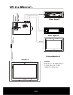
Page 11: ...Video Signal 2 Video Signal 1 CAUTION Please observe the right polarity of the connections and the right colours of the RCA Plugs Monitor 1 Optional Monitor 2 RCA yellow RCA yellow RCA yellow VIDEO I...

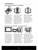
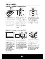
Page 12: ...f the vehicle D Method 2 Installation in Headrest Cut out a sufficient mounting hole in the headrest B Use the inner dimensions of the mounting frame as draft Then lead the A V Cable from the Monitor...

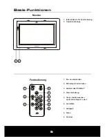
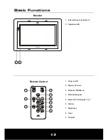
Page 13: ...2 3 4 6 8 7 9 5 1 Power on off 2 Display Overturn 3 Activates OSD Menu 4 Mute Audiosignal 5 Selector for AV Signal 1 or 2 6 Volume 7 Brightness 8 Color 9 Contrast Basic Functions 1 Infrared Sensor fo...

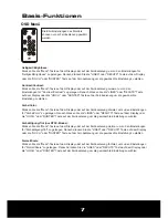
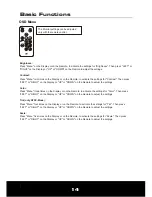
Page 14: ...u three times on the Display or on the Remote to activate the settings for Color Then press LEFT or RIGHT on the Display or UP or DOWN on the Remote to adjust the settings Tint only NTSC Mode Press Me...

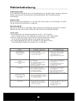
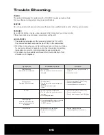
Page 15: ...obable Causes Solution Little regular light spots and color spots on the screen or black horizontal line in the picture 1 No 12 voltage 2 The A V cable of the monitor is loose or is damaged 1 Check if...

Page 16: ...Distribution Audio Design GmbH Am Breilingsweg 3 76709 Kronau Germany Tel 49 0 7253 9465 0 Fax 9465 10 www audiodesign de...

Reviews: