background image

34

Etac / Cross 5 / www.etac.com

1

1

2

2

3

1

1

5

5

Cross 5

Cross 5 XL


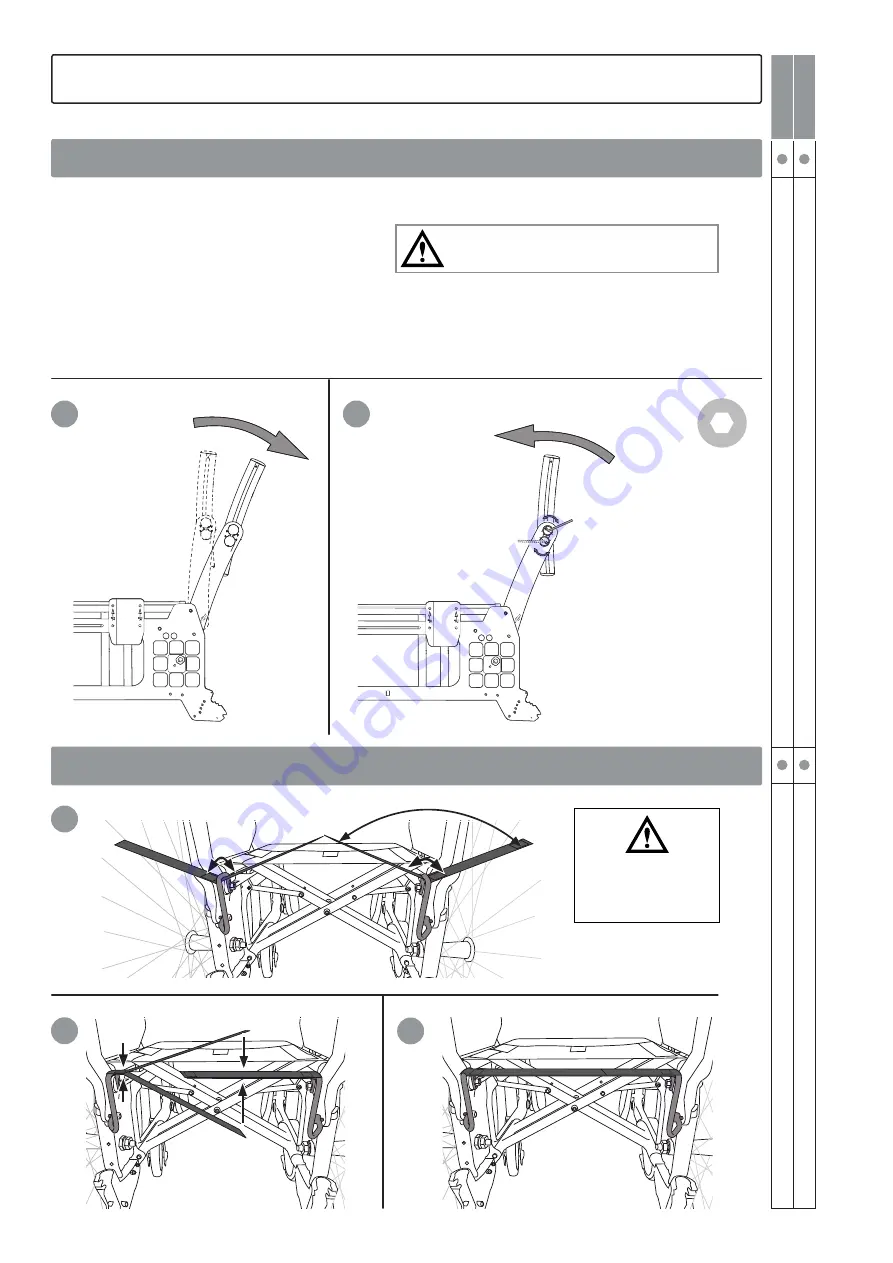
An extended seat depth is achieved by opening 
the back support angle (hip) and then the lumbar 
angle.

1. Adjust the back support angle (see also 

illustra-

tion 1-3 on page 32

).

2. Adjust the lumbar angle to the required back 
support angle using the eccentric shafts as in 

point 4-5 on page 34

.

3. If necessary fit seat extender (accessory)..

Risk of tipping: Always check the setting of the

the anti-tips.

6. Settings back support 3A

 Adjusting seat depth using lumbar angle

Fitting seat extender

5 mm

Risk of tipping: Always 

check the setting of the

the anti-tips.

Summary of Contents for Cross 5 Active

Page 1: ...Etac Cross 5 Etac Cross 5 XL Etac Cross 5 Active Etac Cross 5 Manual english 75190T 18 01 09 ...

Page 2: ...intenance Fault finding chart 30 5 Settings cont Seat angle 31 Seat depth 31 Seat comfort 31 6 Settings back support 3A Adjusting back support angle 32 Adjusting back support height and lumbar angle 33 Adjusting seat depth using lumbar angle 34 Fitting seat extender 34 7 Settings back support mod 2 35 8 Readjustments Brake adjustment 36 Adjusting the brake block 37 Continuously angle adjustable le...

Page 3: ...d contour The foot supports are adjustable in height angle and depth Etac Cross 5 and Etac Cross 5 XL can be supplemented and adjusted if need change A large range of options and accesso ries are available Various types of back support and leg support fixing points for transport in mobility service buses antitips various types of handrims and brakes etc Etac Cross 5 and Etac Cross 5 XL have the be...

Page 4: ...il 4 Handrim 5 User brake 6 Quick release hub 7 Side frame 8 Front fork attachment 9 Front fork 10 Castor wheel 11 Back support cover 12 Back support upholstery 13 Rear wheel 14 Cross frame 15 Seat upholstery 16 Leg support 17 Serial number 18 Locking knob foot support 19 Foot support 20 Brake handle drum brake 21 Cross brace 22 Brake wire drum brake ...

Page 5: ...or wheel 4 massive max user weight 100 kg 5 massive with Cross 5 XL max user weight 135 kg 6 semipneumatic 6 5 massive 7 massive soft 8 semipneumatic Front fork Extra short two alternative wheel height positions Short three alternative wheel height positions Medium three alternative wheel height positions Long Rear wheel 20 22 24 24 Carbon not in combination with drum brakes 26 Handrims Aluminium ...

Page 6: ...ame 48 54 cm Back support upholstery Adjustable upholstery ECS Back support cover Standard Comfort Tidy water repellent wipeable Push handles Bow handle Height adjustable at intervals of 2 cm Detachable Push handles Bow handle Fixed push handles Right left fits back support 3A Fixed back sup port with fixed push handles 2B Height low back 35 40 Height high back 42 5 47 5 Angle 5 15 Leg supports de...

Page 7: ...rt Leg supports other Plaster leg support Amputee leg support Amputee weight Arm support Short 25 cm Long 35 cm Foot support Std Max length 51 cm Min length 33 cm Extended attachment tubes 10 cm Shorter attachment tubes 8 cm One piece foot support One piece foot support complete for 35 37 5 seat width adjustable in angle settable height and depth Front fork attachment 6 cm Low widened Standard wid...

Page 8: ...ion Hemi swing away for mounting on long arm supports Arm support Locking Kit A locked arm support is not detachable but its height can be adjusted freely Arm support foldable height adjustable or fixed height not with telescopic anti tips Use anti tips for Etac Cross 5 Active Side guard black Mudguard right and left Thigh support 4 Accessories 3 The chair s possibilities Cross 5 Cross 5 XL Drum b...

Page 9: ...ther with triangular back Seat cushion dark grey plush and black velour 56 cm cut according to seat depth set washable Seat cushion Tidy water repellent wipeable Comfort wedge for the cushion evens out the front part of the seat Cover for calf support on angle adjustable leg support model 3 black Dartex Calf strap detachable black nylon adjustable in length Padding for calf strap Calf support Plus...

Page 10: ...wedge Three different sizes attached with Velcro Provides support and contour The wedges can also be combined with other accessories and cut to desired size Several wedges can also be put together Back wedge length 15 and 30 cm attached with Velcro Side cushion Provides gentle lateral support Used when the trunk support is too stabilising Combined with arm support and if necessary side stop Side s...

Page 11: ...stable length and angle not with foldable arm supports Anti tips For Etac Cross 5 Active Cane holder two parts one of which is an elasticated section that is fastened around the cane Drip stand Bracket and stand Spoke guard with grey or yellow print Tetra quickrelease adapter for persons with reduced hand function Tool kit Bags Gloves Information is available at www etac com ...

Page 12: ...e screws on one front fork mounting Use the position markings as a reference for adjusting the height on the other side Tighten the other mounting Check and adjust so that the mountings are perpendicular See section Angle setting of front fork mounting Fine tune the height of the front fork mountings so that both wheels are flush with the floor Risk of tipping Always check the setting of the the a...

Page 13: ...ls use the Transit fork gives a seat height of 47 51 cm With Cross 5 XL max user weight 135 kg Cross 5 Cross 5 XL Adjusting the front seat height by changing the castor wheel front fork Front seat height table 5 Settings 5 mm 19 mm G F E D C B A 6 5 4 3 2 1 1 2 3 Castor wheel position cm Front fork extra short Front fork short Front fork medium Front fork long Rear wheel pos Castor wheel 1 2 3 1 2...

Page 14: ...f the castor starting to wobble Mount the cover plug Mounting front fork 19 mm 5 Settings Cross 5 Cross 5 XL The correct angle setting is important for the wheelchair s manoeuvrability Unscrew the lower attachment screw A about 2 turns so that the shaft C moves freely inside the sleeve Insert the Allen key in the hole B and turn until the attachment is 90 to the floor Always start from a position ...

Page 15: ...hanging the rear wheel Risk of tipping Always check the setting of the the anti tips 1 Remove the rear wheel 2 Unscrew the nut 3 Reassemble in desired position see table in section Rear seat height table Risk of tipping Always check the setting of the the anti tips 5 Settings Adjusting rear seat height by changing rear wheel position or rear wheel size Rear seat height 24 mm Cross 5 Cross 5 XL ...

Page 16: ...A 6 5 4 3 2 1 1 2 E C A 1 3 5 Cross 5 Cross 5 XL 5 Settings When assembling check so that the rear wheel axle is correctly adjusted The button in the hub must pop out to the original position Assembly in pos G1 G2 24 mm 17 mm Assembly 0 Camber ...

Page 17: ...cm 6 5 cm 22 46 5 cm 9 0 cm 24 49 cm 11 5 cm 26 51 cm 14 cm Position C 20 42 cm 8 5 cm 22 44 5 cm 11 0 cm 24 47 cm 13 5 cm 26 49 cm 16 cm Position D 20 40 cm 10 5 cm 22 42 5 cm 13 0 cm 24 45 cm 15 5 cm 26 47 cm 18 cm Position E 20 38 cm 12 5 cm 22 40 5 cm 15 0 cm 24 43 cm 17 5 cm 26 45 cm 20 cm Position F 20 36 cm 14 5 cm 22 38 5 cm 17 0 cm 24 41 cm 19 5 cm 26 43 cm 22 cm Position G 20 34 cm 16 5 ...

Page 18: ...D2 C1 C2 B1 B2 A1 A2 F3 F4 E3 E4 D3 D4 C3 C4 B3 B4 A3 A4 F5 F6 E5 E6 D5 D6 C5 C6 B5 B6 A5 A6 E D C B A 1 2 3 4 5 6 2 1 Pos A6 Pos F3 F6 Pos G1 G2 Pos A1 5 B E F1 F2 Drum brake Cross 5 Cross 5 XL 5 Settings To adjust the brakes loosen nut A Loosen tighten screw B in order to reach proper brake function Tighten the nut A This adjustment should be done when the brakes are not working properly 8 mm Th...

Page 19: ...c com Etac Cross 5 Etac Cross 5 XL Etac Cross 5 Active 75190T 18 01 09 User manual This part of the manual User manual should be torn out and at all times follow the wheelchair This as it contains impor tant user information ...

Page 20: ...nd in the user manual Securing Removable part do not lift Risk of tipping Always have the anti tips down when in motion Pinch point hazard After adjusting seat height centre of balance back support angle or back support upholstery the anti tips function must always be checked General warnings The following should be taken into account in any use of the product Max tilt up excl anti tip 6 Bright su...

Page 21: ... can be removed without tools shall be removed and secured A correctly adjusted head support shall be used The back support shall be level with or above the user s shoulders Cross brace or head support attachment 3A must be used Cross 5 Cross brace must be used Cross 5 XL Rear wheels must have handrims 3 According to directive 2001 85 EC appendix VII point 3 8 3 there are specially marked wheelcha...

Page 22: ...nual Unfolding Push down on one side of the seat frame using the whole of the flat of the hand Do not hold the seat frame tube while unfolding as there is a risk of pinching your fingers Lower the foot supports Anti tips The anti tips can be flipped up Ensure the locking function works properly when activa ting the anti tip After any adjustments on your wheelchair always ensure that you check the ...

Page 23: ...r is to be lifted with the user sitting in it Make sure the safety button pops out below the bracket The bow handle must be removed before the chair can be folded Leg support The leg supports can be removed swung to the side if needed Lockable leg supports by pushing the red button A To fasten the lockable leg supports press down on the red button A put the leg support into place and release the b...

Page 24: ...vis by tightening the strap found just below the lumbar region Then adjust the upper strap to provide the user with upper body support and balance The other straps are adjusted to provide space for the user s posterior and follow the back s natural curvature Risk of tipping Always check the setting of the the anti tips Do not overtighten the upper straps as this can prevent the cross brace from un...

Page 25: ... and pull out the screw Set the height Assemble the screw and knob and tighten firmly Arm support adjusting Loosen the screw on the inside of the arm support plate Set the required height and tighten the screw The high position of the arm supports supports and relieves pressure on the back better than a lower position 5 mm 3 mm Settings seat comfort User manual Calf heel strap Adjust the length so...

Page 26: ...rly tightened Swing non lockable leg supports in under the seat and lift the wheelchair by the front upper part of the frame User manual Driving technique maneuvering Never stand on the foot supports as there is a risk of tipping Never park on a slope with a user in the wheelchair Turn the castor wheels forwards and activate the brakes Turn the castor wheels forwards activate the brakes flip up th...

Page 27: ... technique is recommended only for experienced wheelchair users Ensure that the anti tips are deactivated User down backwards This technique is recommended only for experienced wheelchair users Ensure that the anti tips are deactivated User manual The following figures show principles for propelling techniques and how to overcome obstacles like steps and curbs Activate the anti tips afterwards Act...

Page 28: ... afterwards Activate the anti tips afterwards Care giver up forwards Ensure that the anti tips are deactivated Care giver up backwards Ensure that the anti tips are deactivated Care giver down forwards Ensure that the anti tips are deactivated Care giver down backwards Ensure that the anti tips are deactivated User manual ...

Page 29: ...hese are lockable Stairs up Ensure that the anti tips are deactivated Never use an escalator even if a care giver is available Ensure that height adjustable push handles are tightened We always recommend using two carers for this transfer One who walks behind and holds on to the push handle and one who walks in front and holds on to the frame or in the leg supports if these are lockable Ascending ...

Page 30: ...vy to propel Pump up the tyres Rear wheel mountings are incorrectly fitted Clean the castor axles from hair and dirt Too much weight over the castors Adjust the centre of balance The wheelchair feels heavy to turn Pump up the tyres Check that the front fork attachments are not too tight Check and adjust the angle of the front fork attachments Clean the castor axles from dirt Too much weight over t...

Page 31: ... front seat upholstery and sliding it backwards or forwards With Cross back support 3A triangular the seat depth can be further adjusted by means of the lumbar angle see the section Adjusting seat depth using lumbar angle triangular back Risk of tipping Always check the setting of the the anti tips 5 Settings Seat angle Seat depth Seat comfort After adjusting seat height seat angle seat depth and ...

Page 32: ...2 Adjust the back support angle Use the position mark ings to obtain the same back support angle on the right and left sides respectively 3 Tighten the nut Risk of tipping Always check the setting of the the anti tips 6 Settings back support 3A Adjusting back support angle 13 mm ...

Page 33: ...ed upper recommend ed eccentric shaft s locking screw and loosen it 1 2 turn Move the Allen key to the eccentric shaft s key handle and set the required lumbar angle 4 Tighten the locking screws with 6 Nm We recommend that you start adjusting the lumbar angle with the upper eccentric shaft If a larger angle is required adjust the lower eccentric shaft as well Risk of tipping Always check the setti...

Page 34: ...o illustra tion 1 3 on page 32 2 Adjust the lumbar angle to the required back support angle using the eccentric shafts as in point 4 5 on page 34 3 If necessary fit seat extender accessory Risk of tipping Always check the setting of the the anti tips 6 Settings back support 3A Adjusting seat depth using lumbar angle Fitting seat extender 5 mm Risk of tipping Always check the setting of the the ant...

Page 35: ...hten the straps in such a way that they follow the contours of the user s back and give plenty of support to the lumbar region Do not overtighten the upper straps as this can prevent the cross brace from unfolding properly i e the seat frame tubes do not sit flush in the sideframes Risk of tipping Always check the setting of the the anti tips The back support angle is infinitely variable See The c...

Page 36: ...r s back and give plenty of support to the lumbar region Do not overtighten the upper straps as this can prevent the cross brace from unfolding properly i e the seat frame tubes do not sit flush in the sideframes Risk of tipping Always check the setting of the the anti tips The back support angle is infinitely variable See The chairs possibilities The angle is adjusted using the nut on the inside ...

Page 37: ...e tyres The brakes are parking brakes and should not be applied during use If the rear wheel is positioned in one of the forward settings it is possible for a leg support when swung to the side to unlock an applied brake To avoid this the brake handle should be adjusted so that you attain a neutral position In this way the brake will unlock first when the handle is pushed close to the rear wheel 1...

Page 38: ...ting a wheelchair swing in the leg supports under the seat or remove them and lift using the frame lower or upper part Always have the screw and knob for foot sup port attached even if not using foot support 8 Readjustments Leg support infinitely angle adjustable Adjusting the brake block 5 mm Cross 5 Cross 5 XL ...

Page 39: ...ight centre of balance back support angle or back support upholstery the anti tips function must always be checked 8 Readjustments Anti tips 5 mm Never sit on the amputee leg support When lifting the wheelchair remove the amputee leg support swing the other leg support in under the seat or remove it and lift using the frame lower or upper part Amputee leg support 4 mm 6 mm ...

Page 40: ... wheel position or rear wheel size The centre of balance is also altered when the seat and or back support angle is adjusted We recommend the use of anti tips Ensure that rear wheels with quick release hubs are mounted securely The camber angle can be changed by changing the washers that are mounted between the hub sleeve and the nut See section Adjusting rear seat height by changing rear wheel po...

Page 41: ...e that when passing through narrow spaces there is a risk of getting your fingers caught There is also a risk of fingers getting caught in the spokes If there is a risk of the user s fingers getting caught in the spokes we recommend spoke guards Aluminium stainless plastic coated and cellular rubber handrims for 24 22 and 20 rear wheel The distance between the wheel and the handrim can be adjusted...

Page 42: ... position 1 the height of the arm support is settable between 19 and 26 cm and in position 2 standard between 24 and 31 cm with 1 cm intervals 10 mm 5 mm The lock lug is used both to set the height of the arm support and secure the side guard Loosen the screw that fastens the lock lug Slide the guard up or down to the desired height Refasten the lug on the side guard If necessary the right arm sup...

Page 43: ...en the screws again Never use the arm supports to lift the wheel chair These arm supports cannot be combined with cane holder or with 24 22 or 20 rear wheels in position C The positioning belt is in two parts is adjustable in length and has a snap lock It is mounted in the holes just in front of the back support joint above the wheel mounts Assembly instructions are supplied with the belt The belt...

Page 44: ...achable Before the head support is adjusted ensure that the user has a good secure sitting posture Check the balance of the wheelchair when the user leans against the head support We recommend the use of anti tips Head support attachment Cross brace The cross bar is used when the back chassis needs to be reinforced Do not lift the wheelchair by the cross bar The head support attachment is used to ...

Page 45: ...hort 13123005 61 0 36 42 15 2 kg 135 kg 40 cm long 13123006 61 0 42 48 15 4 kg 135 kg 42 5 cm short 13123007 63 5 36 42 15 3 kg 135 kg 42 5 cm long 13123008 63 5 42 48 15 5 kg 135 kg 45 cm short 13123009 66 0 36 42 15 5 kg 135 kg 45 cm long 13123010 66 0 42 48 15 7 kg 135 kg 47 5 cm short 13123011 68 5 36 42 15 6 kg 135 kg 47 5 cm long 13123012 68 5 42 48 15 8 kg 135 kg 50 cm short 13123013 71 0 3...

Page 46: ... for Cross wheelchairs If there is a fault in your wheelchair you should contact your dealer or Technical Aids Centre Defective wheel chairs should not be used If your chair needs reconditioning or repair only original parts from Etac or components with equal quality as specified in Cross diagrams should be used Etac will not be held responsible for damage or injury caused by use of non original p...

Page 47: ...ed but a maximum of 10 years If the product is intended for use after the service life period specified by Etac it is the responsibility of the prod uct owner to ensure product functionality in accordance with the manual and reconditioning instructions If this cannot be ensured then the product should be taken out of use Methods of surface treatment Lacquered surfaces Polyester powder coating or E...

Page 48: ...3 05 info holland etac com www etac com Etac UK Limited 29 Murrell Green Business Park London Road Hook Hampshire RG27 9GR United Kingdom Tel 01256 767 181 Fax 01256 768 887 info etacuk com www etac com R82 UK Limited Unit D4A Coombswood Business Park East Coombswood Way Halesowen West Midlands B62 8BH United Kingdom Tel 0121 561 2222 Fax 0121 559 5437 enquiries etac uk r82 com www etac com Etac A...

Reviews: