background image

4

Etac / Cross 6 / www.etac.com

Transport in vehicles

The product is crash tested and approved according to ISO 7176-19 

(see section 

“CE marking, tests”

 in the manual). 

Etac recommends in the following order:

1)  The user moves to a vehicle seat and uses the vehicle’s three-point 

belt during transport. The wheelchair is then placed securely in the 

luggage compartment or in the back seat so that it can’t overturn 

or roll.

  The wheelchair should primarily be placed in the 

luggage compartment.

  If the wheelchair is placed in the back seat, make sure 

it can’t overturn or roll. If possible, secure it with the 

car’s seat belt.

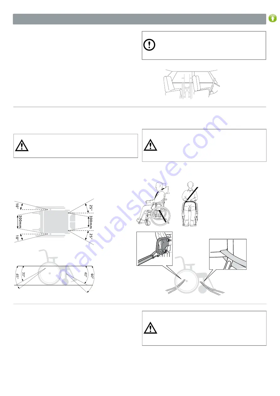
2)  The wheelchair is anchored forward in the vehicle according to 

this manual, the user uses a separate three-point belt that is 

anchored in the vehicle. This is the way the wheelchair is tested 

and approved according to ISO 7176-19.

Anchoring

• 

 Rear transport bracket must be used

  The anchoring device must not be pulled through 

the wheels or around the back posts.

 See section 

“CE-marking, tests”

  Accessories that can be detached without tools must 

be removed and clamped

  If head support is mounted other than with head 

support bracket 3A, cross bar must be used

3)  Pursuant to Directive 2001/85/EC, Annex VII, point 3.8.3. in 

vehicles, there may be specially marked wheelchair spaces that 

allow transport with the wheelchair facing the direction of travel. 

If this mode of travel is used, the user/attendant must be active 

in the ride, be prepared for sudden movements and have the 

ability to maintain a safe sitting position throughout the transport. 

The user’s disability must not be to such an extent that he cannot 

hold on himself and the wheelchair to the handle mounted in the 

vehicle in the event of changes in speed or direction.

 The parking brake must be used

 Anti-tip guard must be folded down

  Add-on options/accessories that can be detached 

without tools must be removed and clamped.

 A properly set head support must be used

 Positioning belt should be used

2. Safety

Summary of Contents for Cross 6

Page 1: ...Etac Cross 6 Manual English 75401C 201216...

Page 2: ...dling Folding unfolding 11 Rear wheels with quick release axle 11 Anti tip guard 11 Tilter 11 Leg supports 12 Push handles bow handle height adjustable 12 Attendant brake service brake parking brake 1...

Page 3: ...and reconditioning manual The actual life span may vary depending on how much and inten sively the product is used but is a maximum of 10 years If the product is intended to be used after the life sp...

Page 4: ...The anchoring device must not be pulled through the wheels or around the back posts See section CE marking tests Accessories that can be detached without tools must be removed and clamped If head sup...

Page 5: ...Wash as per the washing instructions on the product Chassis handle and arm supports Everyday maintenance Clean the chassis with commonly used cleaning agents without abrasives that have a pH value be...

Page 6: ...m 15 5 kg 52 5 cm short 13240115 73 0 cm 36 49 cm 15 4 kg 52 5 cm long 13240116 73 0 cm 42 55 cm 15 6 kg Weights apply to a chair with 24 rear wheels high pressure tyres aluminium hand rims handles le...

Page 7: ...x backward angle 6 cm higher than back 9 Castor wheel 4 solid max user weight 100 kg 5 solid 6 semi solid 6 5 solid 7 solid soft 8 semi solid or air pumped Front fork Extra short two height positions...

Page 8: ...dy wipeable Push handles Bow handle Height adjustable push handles with 2 cm intervals Detachable Height adjustable bow handle with 2 cm intervals Detachable Fixed push handles Ri le fits Cross back s...

Page 9: ...shion Tidy Water repellent wipeable Comfort wedge For the cushion levels off the front of the seat Cover for calf plate On elevating leg support black Hygiene Calf strap Detachable black nylon adjusta...

Page 10: ...rt The wedges can also be combined with other accessories and adapted to the desired size and several wedges can be built together 13x9 5x2 cm 19x12x2 cm 20x17x2 5 cm Dark grey plush 15 cm 30 cm Side...

Page 11: ...ld down the foot plates Anti tip guard The anti tip guards are foldable in two locking positions The first locking position may be required if the anti tip guard pushes against the back chassis When u...

Page 12: ...ition Make sure the handles are in a snap in position lock the locking handle Make sure the locking handles are properly locked This is especially important when lifting the wheelchair with the user i...

Page 13: ...rovided For a more contoured seat cushion it can be supplemented with a comfort wedge which is placed in the pocket on the underside of the seat cushion Back cover Slacken all back straps but make sur...

Page 14: ...of the foot plates so that the ankles are at a 90 angle Height adjustment Loosen the locking knob completely on the leg support Undo the screw Adjust the height Install screw and knob Tighten properly...

Page 15: ...roperly locked Non lockable leg supports are swung in under the seat and the wheelchair is lifted at the front upper part of the frame Never stand on the foot plates risk of tipping Do not park on a h...

Page 16: ...nique is only recommended for experienced wheelchair users Make sure the anti tip guards are inactive User down backwards This technique is only recommended for experienced wheelchair users Make sure...

Page 17: ...terwards Activate the anti tip guards afterwards Attendant up forwards Make sure the anti tip guards are inactive Attendant up backwards Make sure the anti tip guards are inactive Attendant down forwa...

Page 18: ...Never use escalators even if there is an attendant Make sure that height adjustable handles are tightened We recommend that there always be two attendants in this move One who goes behind and holds t...

Page 19: ...ment G 4 34 38 35 5 39 5 Low front fork attachment A F 5 36 40 37 5 41 5 39 43 6 41 45 Standard Wid ened front fork attachment A F 5 37 5 41 5 39 43 40 5 44 5 43 46 45 48 46 49 6 40 44 41 5 45 5 45 47...

Page 20: ...8 Position E 20 38 12 5 22 40 5 15 24 43 17 5 26 45 5 20 Position F 20 36 14 5 22 38 5 17 24 41 19 5 26 43 5 22 Position G 20 34 16 5 22 36 5 19 24 39 21 5 26 41 5 24 Position H 20 32 18 5 22 34 5 21...

Page 21: ...he height of the front fork attachments so that both wheels are on the floor Consider the risk of tipping Always check the setting of the anti tip guard 6 mm 20Nm Angle setting front fork attachment C...

Page 22: ...d The washer C is placed with a beveled side against the axle Spring washer D at the top under the lock nut Gently tighten the lock nut until the front axle spins with some inertia and then loosen abo...

Page 23: ...on Change rear wheel position 1 Remove the rear wheel 2 Loosen the nut 3 Take the assembly apart with the washers and mount in the desired position see table in section Rear seat height table Consider...

Page 24: ...B A 6 5 4 3 2 1 G E C A 3 1 5 12 Advanced settings customization When fitting check that the rear wheel hub shaft is correctly set The button in the hub should spring out to its original position Tes...

Page 25: ...E2 E1 D2 D1 C2 C1 B2 B1 A2 A1 G H F E D C B A 6 5 4 3 2 1 Pos A6 Pos G1 G2 Pos A1 5 B E F1 F2 Pos F3 F6 G3 G4 H3 H4 Pos A6 Pos F3 F6 G3 G4 H3 H4 Pos G1 G2 Pos A1 5 B E F1 F2 12 Advanced settings cust...

Page 26: ...lso be adjusted between the click positions 3 Tighten the nut Consider the risk of tipping Always check the setting of the anti tip guard 13 mm Adjust the back support height and lumbar angle 3A The b...

Page 27: ...the back angle see section Adjusting the back support angle 3A 2 Adjust the lumbar angle using the eccentric sleeve to the desired back angle see Adjusting the back support height and lumbar angle 3A...

Page 28: ...Adjust the back angle 2B The angle of the back support is continuously adjustable see The chair s possibilities The angle is adjusted by means of the nut on the inside of the rear wheel mounts Loosen...

Page 29: ...pressure The brake is a parking brake and should not be used as a driving brake If the rear wheels are mounted in one of the front positions leg supports that are folded aside can release locked brak...

Page 30: ...support can be adjusted Never sit on the amputee support When lifting a wheelchair remove the amputee support fold the other leg support under the seat or remove it and lift the frame lower or upper...

Page 31: ...grip possibilities Foam rubber and plastic are available as an option Foam rubber plastic handrims give higher friction In the event of heavy braking slight burns e g blisters may occur Risk of crush...

Page 32: ...gle Use of anti tip guards is recommended When assembling rear wheels always make sure that the quick release button in the hub springs out properly Test by pulling the wheel Toe in toe out Due to the...

Page 33: ...ht of the arm support and attaches the side plate Loosen the screw holding the square nut Slide the side plate up or down to the desired height Tighten the nut again on the side plate If necessary the...

Page 34: ...case on the underside of the cushion The arrow on the comfort wedge should be facing up and pointing forwards Installation instructions are always included with the accessories when delivered from Et...

Page 35: ...support make sure that the user has a good sitting position and is seated firmly Check the wheelchair balance when the user leans his head against the head support Use of anti tip guards is recommend...

Page 36: ...04 39 info holland etac com www etac com Etac UK Limited 29 Murrell Green Business Park London Road Hook Hampshire RG27 9GR United Kingdom Tel 01256 767 181 Fax 01256 768 887 info etacuk com www etac...

Reviews: