Hardware
12
2.1.1
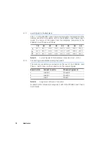
Load Signals to the Backplane
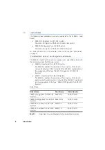
Slots 1 - 3 of the ES4408.1 Load Chassis are intended for the integration of the
injection loads (for more details, refer to the ES4408.1 Load Chassis) User’s
Guide. The supply of the signals from the backplane connectors of the
ES4408.1 Load Chassis is as follows:
Tab. 2-1
Current Signals of the Backplane Connectors Slot 1...Slot 3
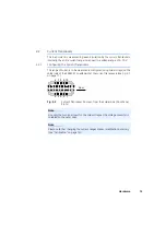
2.1.2
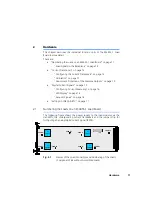
Connecting Loads and Measuring the Signals
The loads are connected via connectors on the rear of the ES4408.1 Load
Chassis - next to them are the connectors for the measure signals.
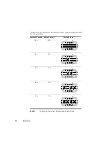
Tab. 2-2
Assignment of Slots to Connectors
For details of the individual pin assignment, refer to the ES4408.1 Load Chassis
User’s Guide.
18
20
22
24
26
28
30
32
z
Load 1+
Load 1-
Load 2+
Load 2-
Load 3+
Load 3-
Load 4+
Load 4-
b
Load 1+
Load 1-
Load 2+
Load 2-
Load 3+
Load 3-
Load 4+
Load 4-
d
Load 1+
Load 1-
Load 2+
Load 2-
Load 3+
Load 3-
Load 4+
Load 4-
Board in Slot
Connect Load to
Measure Signals at
1
Load 8-2
Meas 8-2
2
Load 8-1
Meas 8-1
3
Load 7
Meas 7
Summary of Contents for ES4455.1
Page 1: ...ES4455 1 Load Board User s Guide ...
Page 10: ...Introduction 10 ...
Page 24: ...Technical Data 24 ...
Page 26: ...ETAS Contact Addresses 26 ...


