Hardware
16
2.3.1
Configuring Current Measuring
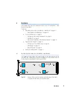
Current measuring (for all loads installed on the carrier board) is configured
using the “JP200” jumper strip.
Fig. 2-1 on page 11 shows the position of the jumper strip on the board – this
is only accessible when the rear load is removed.
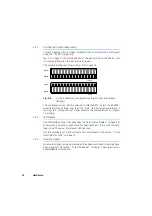
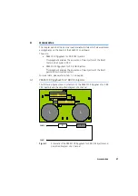
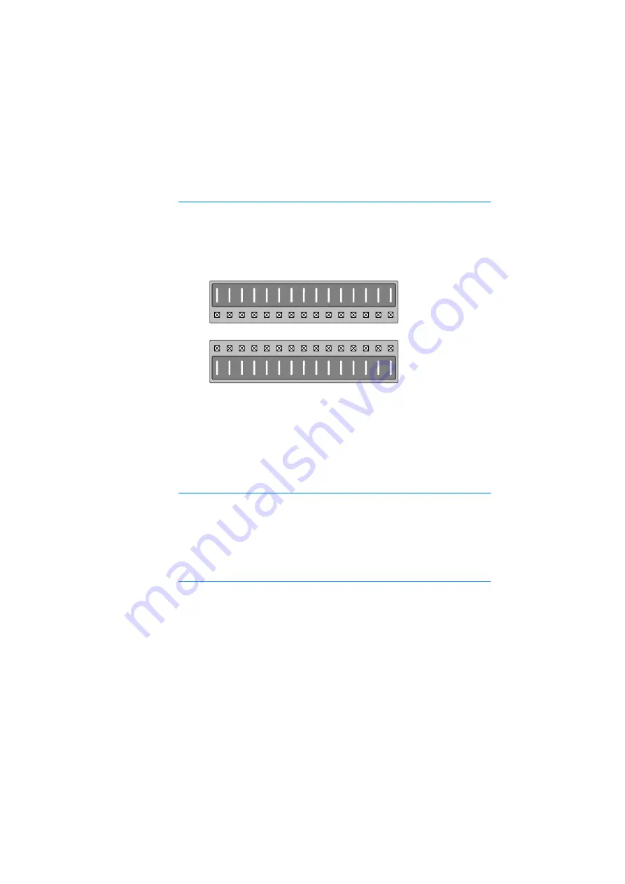
The possible settings are shown in Fig. 2-4 on page 16.
Fig. 2-4
Current Measuring Configurations: Digital (Top) and Analog
(Bottom)
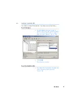
The configuration can also be queried in LABCAR-RTC. Select the ES4455-
Load-Carrier Device there, and then the “Data” tab. When an experiment is
running, the “JumperSetting” signal contains the configuration: 0 = digital,
1 = analog.
2.3.2
LED Display
The LED display on the front panel (see "LEDs for Status Display" on page 20)
shows when a specific current value has been reached – if the current over a
load is over this value, the relevant LED lights up.
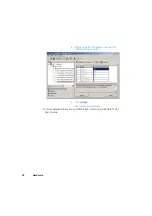
The thresholds are set in the software; this is described in the section "To set
thresholds for LEDs" on page 17.
2.3.3
Acoustic Signals
An acoustic signal can be emitted when the above-mentioned thresholds have
been attained. The section "To set the beeper" on page 17 describes how to
enable/disable this function.
Digital
Analog
JP200
Digital
Analog
JP200
Summary of Contents for ES4455.1
Page 1: ...ES4455 1 Load Board User s Guide ...
Page 10: ...Introduction 10 ...
Page 24: ...Technical Data 24 ...
Page 26: ...ETAS Contact Addresses 26 ...

