ES5338.1 Carrier Board for Wheel Speed Sensor Simulation - User’s Guide
23
ETAS
Design, Installation and Fuses
2.4
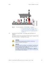
Assembly of Piggyback
This chapter describes how the PB5338CURR.1-A Wheel Speed Sensor Simula-
tion Piggyback are installed on an ES5338.1 Carrier Board.
CAUTION!
Some components of the ES5338.1 Carrier Board can be damaged or
destroyed by electrostatic discharges. Leave the plug-in card in its
transport packaging until its installation.
The ES5338.1 Carrier Board and the PB5338CURR.1-A Piggyback
should only be removed, configured and installed at a workplace that
is secured against static discharges.
CAUTION!
The ES5338.1 Carrier Board is designed exclusively for the ETAS
PB5338CURR.1-A Piggyback.
The installation of non-supported boards can lead to damages of the
ES5338.1 Carrier Board, the ES5300.1-A Housing or ES5300.1-B
Housing and/or the non-supported board.
CAUTION!
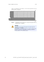
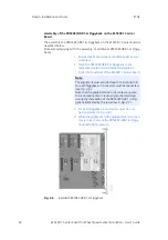
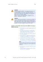
Ensure that the components are subject to the least possible mechan-
ical stress. Tighten the nuts only slightly (approx. 0.3 Nm). Note that
the guide bolt does not contact any electronic components or create
any mechanical stress during the installation of the PB5338CURR.1-A
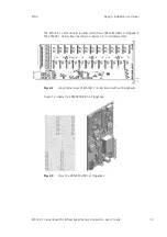
(indicated by a red flash in Fig. 2-7).
Excessive mechanical stress of the components can lead to malfunc-
tions of the ES5338.1 Carrier Board and the PB5338CURR.1-A Piggy-
back, which can cause property damages and personal injuries.

