ES5338.1 Carrier Board for Wheel Speed Sensor Simulation - User’s Guide
27
ETAS
Simulated Sensor Signals
3
Simulated Sensor Signals
This chapter describes the sensor signals that can be generated with the
ES5338.1 Carrier Board.
The ES5338.1 Carrier Board can simulate one sensor of the following types for
each populated PB5338CURR.1-A Piggyback:
• "DF10 and DF11s" on page 29
• "DF11i" on page 29
• "VDA" on page 31
• "PSI5" on page 32
• "Direct Current Output" on page 32
With Direct Current Output, the current source is directly controlled by the sim-
ulation model.
3.1
Creating Real Sensor Signals in the Vehicle
The wheel speed sensor types DF10, DF11s, DF11i and VDA listed above are
active digital sensors. The real wheel speed sensors generate the signals using
the magneto-resistive effect or the Hall effect. When passing an pick-up wheel
(ferromagnetic gear wheel or punching sheet or wheel with attached multi-
poles), the resistance or the Hall voltage of the sensor element changes. This
change is based on the change of magnetic field strength at the sensor element.
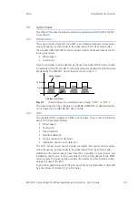
An analysis electronics outputs digital rectangular current pulses whose fre-
quency is proportional to the wheel speed.
The magnetic field strength at the sensor element can also be used to detect
tooth voids and assembly errors. The phase of the induced signal provides infor-
mation about the direction of rotation.
This makes the output of additional information in form of PWM signals or addi-
tional data bits possible, depending on the sensor type.
The use of this measuring principle allows determining the speed (distance mea-
surement) of close to v = 0 km/h. This also covers the partially stricter v
min
requirements for the simulation, e.g. of navigation systems, anti-rollback devices,
parking assist systems, etc.
An other series of sensors, e.g. pressure sensors, generate signals based on the
PSI5 standard.
3.2
Generation of Sensor Signals with the ES5338.1 Carrier Board
The ES5338.1 Carrier Board simulates the signals of the aforementioned wheel
speed sensors. The simulated wheel speed sensor signals are generated with the
help of data from a vehicle model that runs on the RTPC. The configuration of
the piggybacks of the ES5338.1 Carrier Board as sensor for the vehicle simulation
model is done via RTIO using LABCAR-OPERATOR (see LABCAR-RTC User's
Guide). With the PCIe Backplane Connector CO200 of the ES5300.1-A Housing
or ES5300.1-B Housings, the relevant vehicle model data are made available to
the ES5338.1 Carrier Board function generator. The ES5338.1 Carrier Board then
generates the corresponding wheel speed sensor signals with the vehicle simula-
tion model data and RTIO settings.
Signals following the PSI5 standard can also be generated by the ES5338.1
Carrier Board.

