ES5338.1 Carrier Board for Wheel Speed Sensor Simulation - User’s Guide
29
ETAS
Simulated Sensor Signals
3.3
Signal Shapes
This chapter describes the wheel speed sensor signals generated by the ES5338.1
Carrier Board.
3.3.1
DF10 and DF11s
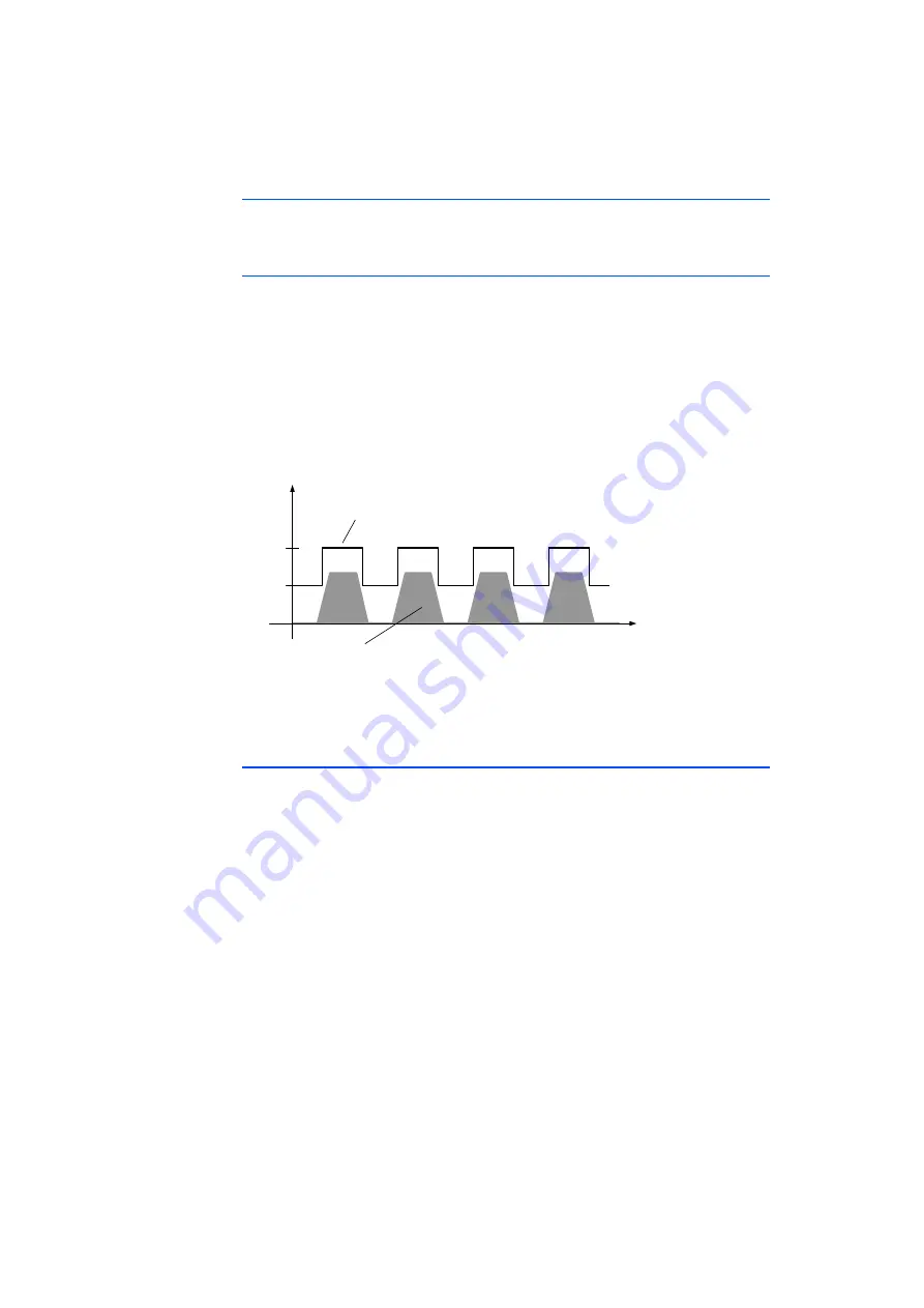
The sensor signals of type DF10 and DF11s are digital rectangular current pulses
whose frequency is proportional to the wheel speed from the vehicle model.
The simulated DF10 and DF11s sensor signals contain information about the fol-
lowing parameters:
• Wheel speed
• Tooth voids
A tooth void pattern can be defined by the user (see LABCAR-RTC Users Guide).
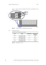
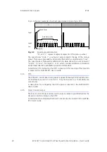
An example of the DF10 or DF11s wheel speed sensor signal without tooth voids
simulated by the ES5338.1 Carrier Board is shown in Fig. 3-1.
Fig. 3-1
Output signal of a simulated sensor of type "DF10" or "DF11s"
The sensor signal can be configured in LABCAR-OPERATOR. A detailed descrip-
tion is located in the LABCAR-RTC User's Guide.
3.3.2
DF11i
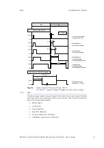
The simulated DF11i signals are PWM current pulses. They contain information
about the following parameters:
• Wheel speed
• Tooth voids
• Travel direction
• Standstill detection
• Air gap reserve error detection
• Installation position error detection
The DF11i wheel speed sensor signals are digital rectangular current pulses
whose frequency is proportional to the wheel speed from the vehicle model.
Additional information about travel direction, standstill, air gap reserve and
installation position are in the pulse duration of the high phases of the PWM
current pulses. The pulse duration consists of multiples of a time interval T
0
defin-
able by the user in the RTIO.
During the segment change of the pick-up wheel, every high phase is preceded
by a low phase of duration T
0
(pre-bit phase).
Sensor Signal
Unfolded Gear Wheel
7 mA
14 mA

