ETAS
Hardware Description
ETK-S20.1
-
User Guide
18
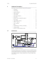
While the microcontroller accesses the data out of the data emulation memory,
the content of the data emulation memory can simultaneously be modified by
the calibration and development system through the serial ETK interface. This
process enables adjustments of parameters, characteristic lines and maps
through the calibration and development system. Using an additional measure
-
ment data memory area, the ECU microcontroller can send data to the calibra
-
tion and development system which receives, buffers and processes this
measured data (DISTAB13).
The 100
Mbit/s serial interface provides communication with the calibration
and development system.
The power supply for the ETK-S20.1 is provided by a switch mode power sup
-
ply, to minimize power dissipation.
4.2
ECU Interface
The ECU interface can be flexibly configured for several applications. For a HDC
update, it is not necessary to unmount or disconnect the ETK-S20.1 from the
ECU.
For currently supported microcontrollers refer to chapter 7.1.3 on
36.
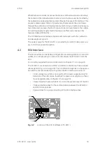
The ETK-S20.1 is connected via CON1 and CON2 to the ECU with two adapter
cables (refer to Fig.
18). The pin definition depends on the applica
-
tion and the microcontroller type. In general the ECU interface consists of
• 1 ECU voltage line, which is not used for ETK power supply but only for
detection of the ECU status, therefore the power consumption on these
line is negligible (refer to chapter
20)
• 1 Reset line which allows the ETK to control the system reset of the ECU
• 7 Debug Interface lines for the communication between the ETK-S20.1
and the microcontroller
• 2 ground lines for a proper shielding of the ECU interface lines.
Fig.
4
-
2
Location of the ECU Interfaces (ETK-S20.1)
CON2
CON1


