ETAS
Technical Data
ETK-S20.1
-
User Guide
45
7.13
Pin Assignment
7.13.1
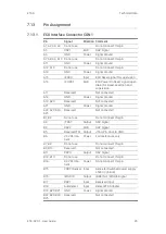
ECU Interface Connector CON1
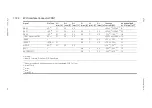
Pin
Signal
Direction Comment
A1; A2; A3; A4
Do not use
Do not connect this pin
A5
DAP1
Bidir
DAP Signal
A6
GND
Power
Signal Ground
A7; A8; A9; A10 Do not use
Do not connect this pin
A11
GND
Power
Signal Ground
A12; A13
Do not use
Do not connect this pin
A14
GND
Power
Signal Ground
A15
/ESR0
Input
ECU Reset signal for supervision
A16
/PORST
Bidir
ECU Power On Reset signal (open
drain) for Reset assertion and
supervision
A17
Reserved
Not connected
A18
GND
Power
Signal Ground
A19; A20
Reserved
Not connected
A21
GND
Power
Signal Ground
A22; A23; A24;
A25
Reserved
Not connected
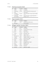
B1; B2
Do not use
Do not connect this pin
B3
/TRST
Output
DAP Signal
B4
DAP2
Bidir
DAP Signal
B5
Reserved TDI Output
JTAG Pin, drive to GND
B6
3.3V Perma
-
nent
Power
For internal use only
B7; B8
Do not use
Do not connect this pin
B9; B10
Reserved
Not connected
B11
DAP0
Output
DAP Signal
B12; B13
Do not use
Do not connect this pin
B14
3.3V Perma
-
nent
Power
Do not connect this pin
B15
VDDP (Sense) Input
Sense for Switched power supply
of ECU (ignition)
B16
/WGDIS
Output
/BRKIN or /WGDIS Signal
B17
RSV1
Input
Reserved Input
B18
Autodetect
Input
Detect ETK Adapter
B19; B20; B21
GND
Power
Signal Ground
B22; B23; B24;
B25
Reserved
Not connected

