ETAS
Technical Data
ETK-S20.1
-
User Guide
40
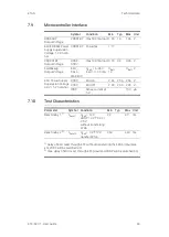
7.9
Microcontroller Interface
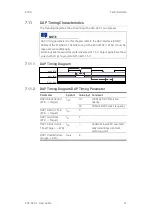
7.10
Test Characteristics
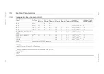
Symbol
Condition
Min
Typ Max Unit
VDDSTBY
Output Voltage
VDDSTBY max 500 mA load 1.23 1.3
1.36 V
ECU ED-RAM Power
Supply Supervision
Voltage. 1.3 V nomi
-
nal
VDDSTBY Powerfail
1.17
VDDPSTBY
Output Voltage
VDDP
-
STBY
max 130 mA load 3.14 3.3
3.46 V
CalWakeup
Output Voltage
ECU_
-
CALL
-
WAKEUP
U
Batt
= 6 - 36 V;
load = 0 - 50 mA
U
Batt
-
1V
U
Batt
V
ECU Power Supply
Supervision Voltage
3.3 V / 5 V nominal
VDDP
ECU on
2.46 2.56 2.66 V
VDDP
ECU off
2.29 2.39 2.49 V
IDDP
Sense current at
5 V
150 µA
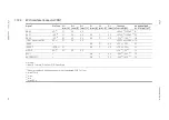
Parameter
Symbol Condition
Min Typ
Max Unit
Reset delay 1
1)
t
Reset1
U
Batt
= 12
V
VDDP = 0
V
3.3
V/
2.5
V
without transferring
FPGA
29
40
ms
Reset delay 2
2)
t
Reset2
U
Batt
= 0
V
12
V
transfer FPGA
360
440 ms
1)
Delay of ECU reset through ETK without transferring the FPGA (U
Batt
pres
-
ent, VDDP will be switched on)
2)
max. delay of ECU reset through ETK (U
Batt
and VDDP will be switched on)

