ETK-S6.0 - User’s Guide
23
ETAS
Hardware Description
4.8
Status LEDs
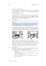
There are three LEDs displaying the operating status of the ETK-S6.0 (Fig. 4-10
on page 23).
Fig. 4-10
Status LEDs (left: Rev. A, right: Rev. B)
4.9
Data Emulation and Data Measurement
In the case of a serial ETK the measurement RAM is part of the ECU and is not
accessible until the ECU is powered up and the basic initialization has been per-
formed. The goal must be to perform the download into the ECU after the ETK's
startup message was sent.
All serial ETKs have a system of Reference and Working Page (ETAS two pages
ETK concept). The Reference Page is located in the ECU flash and can not be
modified by a simple write access. All changes must be done via Flash program-
ming. Due to this a Flash programming algorithm in the ECU and its usage by
ProF is very important for the INCA user.
LED
State
Definition
Red
On
ETK-S6.0 is supplied with power and active (i.e. the ECU is
switched on or the ETAS calibration and development sys-
tem is connected and ready to communicate with the ETK-
S6.0)
Green
Off
Working Page contains valid data and is accessible from
INCA
Flashing ETK-S6.0 is in boot configuration mode:
- measurement and calibration are not possible,
- after first initialization with INCA flashing stops
On
Power supply has dropped under selected threshold:
- data retention of the calibration data manager in the ECU
is no longer ensured
- as soon as the ETK-S6.0 switches on again, the ECU
switches to the Reference Page.
Green LED stays lit until the calibration and development
system downloads data into the calibration data memory.
Otherwise switching to the Working Page is not possible.
Yellow
On
100 Mbit/s communication to calibration system estab-
lished
LED yellow
LED red
LED green
LED green
LED red
LED yellow


