ETK-S6.0 - User’s Guide
18
ETAS
Hardware Description
– 2 ECU voltage lines, which are not used for ETK power supply but only
for detection of the ECU status, therefore the power consumption on
these lines is negligible (refer to chapter 4.6 on page 22)
– 6 ground lines for a proper shielding of the ECU interface lines.
If the debug interface lines between the ETK-S6.0 and the ECU microcontroller
are configured as an AUD-II interface no handshake or trigger pins are needed.
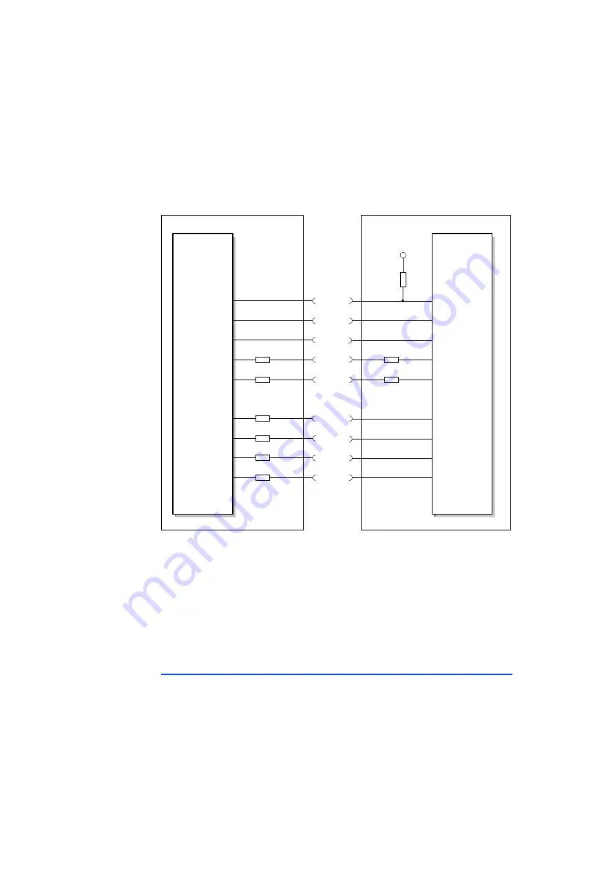
Fig. 4-3
Equivalent Circuitry of the AUD-II Interface
To ensure proper operation of the startup protocol between ECU and ETK the
circuitry has to respect the following topics (refer to Fig. 4-3):
• 22 Ohm series resistors on each of the 4 AUDATA signals, on the AUDCK
and /AUDSYNC signal of the ECU part are recommended.
• The ETK incorporates 22 Ohm series resistors for the /AUDSYNC and
AUDCK lines on the ECU interface.
• The ETK incorporates a 22 kOhm pullup resistor on /AUDRST.
4.3.2
H-UDI Interface
In general the ECU interface configured for H-UDI operation (ETK-S6.0 configu-
ration subtype B, see chapter 6.3 on page 33) consists of
• 8 AUD-II lines for the communication between the ETK-S6.0 and the ECU
microcontroller
• 5 JTAG interface lines which are fed to a separate connector for connec-
tion of an external debugger
AUDMD
AUDATA3
22k
VCCIO
ECU
ETK
/AUDRST
ASEMD
22
22
22
AUDATA2
22
AUDATA1
22
AUDATA0
22
AUDATA3
/AUDRST
ASEMD
AUDMD
/AUDSYNC
22
AUDCK
22
/AUDSYNC
AUDCK
AUDATA2
AUDATA1
AUDATA0
System-
controller
Micro-
controller


