ETK-S6.0 - User’s Guide
20
ETAS
Hardware Description
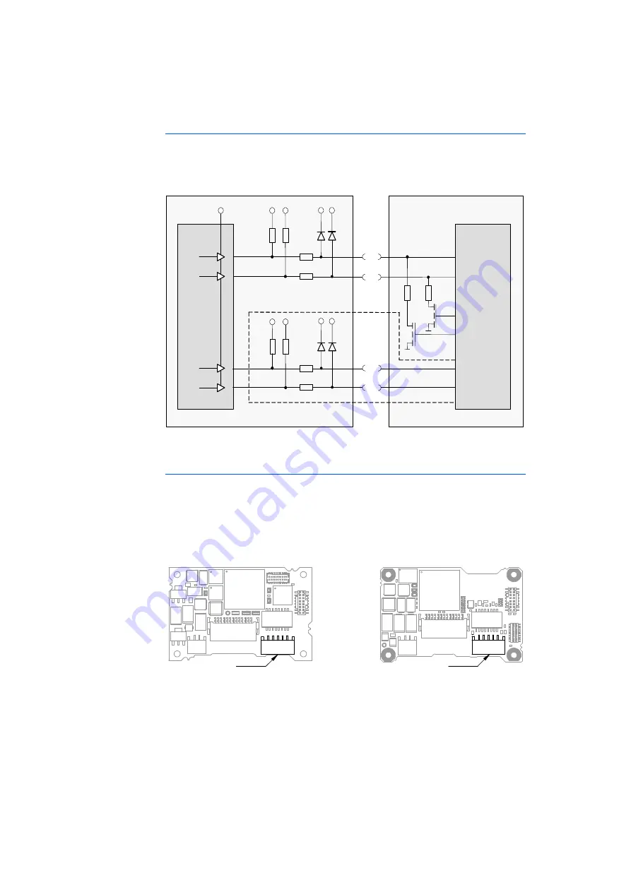
Alternative Voltage Level Shifting Method
An other method to shift the voltages of the DAI ports of the ECU and of the DAI
ports of the ETK at the same level is the usage of diodes and resistors (see
Fig. 4-5 on page 20).
Fig. 4-5
Usage of diodes and resistors
4.4
Serial ETK Interface
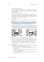
The serial 100 Mbit/s ETK-S6.0 interface creates the link to the calibration and
development system. The interface utilizes a 100Base-TX transmission to achieve
a transmission performance of 100 Mbit/s.
To ensure stable communication only 100 Mbit cables delivered by ETAS shall be
used.
Fig. 4-6
Location of the Serial ETK Interface (left: Rev. A, right: Rev. B)
3k3
3k3
ECU
ETK
PV
CC
(5V)
240
240
33k
33k
PV
CC
(5V)
33k
33k
Optional
PV
CC
(5V)
PV
CC
(5V)
DAI1
DAI2
DAI1
DAI2
PV
CC
(5V)
DAI3
DAI4
DAI3
DAI4
e.g
1N4148
240
240
e.g
1N4148
V
CC
(3.3V)
V
CC
(3.3V)
Micro-
controller
System
Controller
CON4
CON4


