ETK-S6.0 - User’s Guide
22
ETAS
Hardware Description
The ECU part of the JTAG ETK interface is depicted in Fig. 4-8. For proper oper-
ation it is mandatory to provide series termination resistors of 22 Ohm in series
with the TDO line on the ECU PCB.
The ETK incorporates 22 Ohm series resistors for the TMS, TCK, TDI and /TRST
lines on the ECU interface and for TDO line on the debugger connection. Hence,
no additional termination resistors are required on the ECU / debugger PCB for
these signals.
4.6
Power Supply
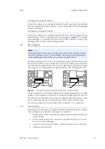
Fig. 4-9
Power Supply Connectors CON2 and CON3 (left: Rev. A, right: Rev.
B)
The ETK-S6.0 needs a permanent power supply. It is powered directly from the
car battery. The input voltage may vary between 4.3 V and 18 V. In case of
higher input voltages to the ETK an additional voltage converter is required.
All necessary voltages are created through switching power supplies which min-
imizes power dissipation. The power supply of the ECU is not affected by the
ETK-S6.0. An automatic switch ensures that the power supply of the ETK-S6.0 is
automatically switched on and off when the ETK enters and leaves its sleep
mode.
The ETK-S6.0 can be supplied with power through the 2-pin power supply con-
nector CON2. The through-hole solder pad CON3 can be used additionally to
connect a power supply U
Batt2
. The power supply on CON3 must use the GND of
CON2 (refer to chapter 5.3.2).
4.7
ECU Voltage Supervisor
The ECU voltage (USG) is monitored by the ETK to recognize whether the ECU is
switched on or off.
Additionally the ECU RAM standby voltage (USGSTBY) is monitored to determine
if the RAM content is still valid. These two signals are only used for monitoring
therefore the load current is negligible.
CON2
CON3
CON2
CON3


