


ETK-S6.0 - User’s Guide
25
ETAS
Hardware Description
the AUDISR and subsequently writes an acknowledgement pattern in another
special register AUDMBR. This is detected by the ETK and signalled to the mea-
surement and calibration system and the measurement data acquisition triggers
are enabled.
Successive phases of the startup protocol
1.
Reset phase:
The ECU is in reset and a special pattern is applied to the
AUDATA lines. At the end of the reset phase the pattern on the AUDATA
lines is latched into the AUDISR register.
2.
ECU Initialization phase:
The ECU performs internal initializations. After
finishing the initializations it writes a special pattern into the AUDMBR
register.
3.
Calibration and data acquisition:
The ECU uses the AUDMBR register
to signal a trigger condition to the ETK, i.e. a measurement raster is ready
for acquisition. The ETK-S6.0 periodically polls the AUDMBR to detect the
triggers. The AUDISR is not used in this mode.
4.10.2
Phases of the Startup Protocol for H-UDI Operation
If the ETK-S6.0 is configured in the ETK Configuration Tool as "ETK-S6.0 Config-
uration B" (see chapter 6.4 on page 34) the ETK is activated for H-UDi operation.
During the startup phase the ETK and the ECU exhibit a well defined startup
procedure.
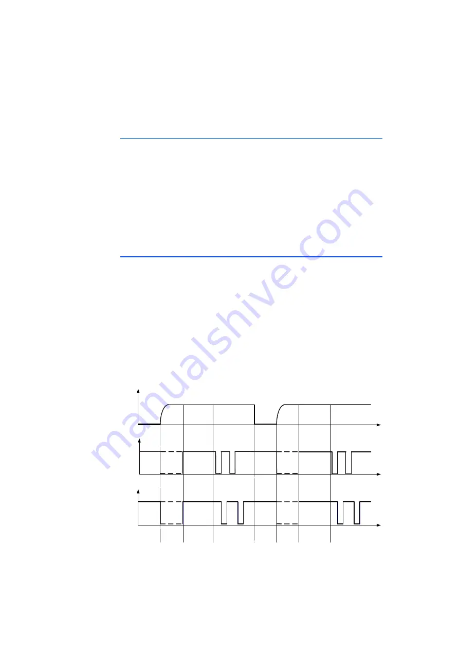
The DAI1 signal is dedicated to ETK detection, i.e. the ETK pulls DAI1 low. If no
ETK is connected, DAI1 will be pulled weakly high via the 33 kOhm pullup resis-
tor on the ECU.
The DAI2 signal is dedicated to signal an ECU Standby power fail of the calibra-
tion RAM. DAI2 high indicates that a powerfail occurred and that the calibration
RAM content has not been restored by the ETK, while DAI2 low indicates no
powerfail.
Fig. 4-11
Phases of the Startup Protocol
Reset
DAI1
DAI2
Phase 1
Phase 2
Phase 3
Phase 4
Phase 1
Phase 2
Phase 4
Phase 3
t
t
t


