ETK-S6.0 - User’s Guide
61
ETAS
Figures
Figures
Adhesive Label (Example: Label for XETK-S14.0) ......................................... 11
WEEE-Symbol ............................................................................................. 12
ETK-S6.0 (left: Rev. A, right: Rev. B) ........................................................... 14
ETK-S6.0 Architecture................................................................................. 16
Location of the ECU Interface (left: Rev. A, right: Rev. B)............................. 17
Equivalent Circuitry of the AUD-II Interface ................................................. 18
Usage of level shifter ICs............................................................................. 19
Usage of diodes and resistors...................................................................... 20
Location of the Serial ETK Interface (left: Rev. A, right: Rev. B) .................... 20
Location of the Debugger Interface (left: Rev. A, right: Rev. B) .................... 21
Equivalent Circuitry of the ECU JTAG Interface (ECU) .................................. 21
Power Supply Connectors CON2 and CON3 (left: Rev. A, right: Rev. B) ....... 22
Status LEDs (left: Rev. A, right: Rev. B) ........................................................ 23
Phases of the Startup Protocol .................................................................... 25
Startup Procedure in Detail ......................................................................... 26
ETK-S6.0 Connection to the ECU ................................................................ 29
ETK-S6.0 Connection to the ECU and to the Debugger............................... 30
Permanent Power Supply inside ECU available ............................................ 31
Permanent Power Supply inside ECU not available ...................................... 31
Isolated Power Supply inside ECU ............................................................... 32
Power Supply Connector CON2 (left: Rev. A, right: Rev. B).......................... 47
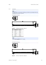
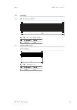
ETK-S6.0 Dimensions - Top View (left: Rev. A, right: Rev. B) ........................ 49
Mechanical Dimensions ETK-S6.0: Microcontroller with Socket Adapter
mounted ................................................................................................... 49
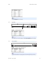
Interface Cable KA54, Proposal 1................................................................ 50
Interface Cable KA54, Proposal 2................................................................ 51
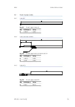
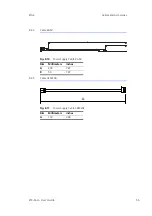
Interface Cable KA41, Proposal 1 ............................................................... 52
Interface Cable KA41, Proposal 2................................................................ 52


