background image

18

ENGLISH

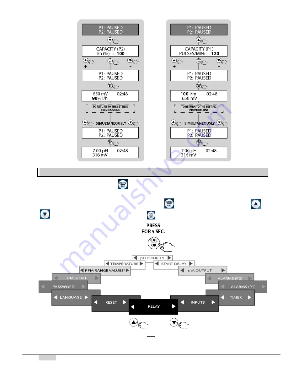
SETTINGS MENU

To access the SETTINGS MENU, press

for at least 5 seconds both from MEASUREMENT mode and from PAUSE.

The following image shows the list of the different items of the SETTINGS submenu which can be accessed. Since it is a circular

menu, the device stores the last item selected before exiting by pressing

. You may scroll the different items using the

and

keys and then selecting the concerned item by pressing

*PPM SCALE VALUES menu only included in the eTwin Cl-pH version

The following paragraphs extensively explain the operating procedures for configuration of the auxiliary functions.

Summary of Contents for eTwin

Page 1: ...E OPERATINGINSTRUCTIONS AND MAINTENANCE NOTICED INSTALLATION EMPLOI ET ENTRETIEN NORMAS DE INSTALACI N USO Y MANUTENCI N NORMAS DE INSTALA O USO E MANUTEN O IT UK FR ES PR eTwin March 2020 Edition GEB...

Page 2: ......

Page 3: ...Main features 5 Technical features of peristaltic version 6 Technical features of electromagnetic version 6 Materials in contact with additive in peristaltic version 6 Materials in contact with additi...

Page 4: ...puts 19 Inputs 21 Timer 21 Alarms 23 mA output 25 Visualization of the probe mVs 25 Activation delay 26 pH priority 26 Temperature 26 PPM scale values 27 Clock 27 Password 28 Setting the language 29 R...

Page 5: ...smust bemade within10 days ofarrival ofthe goods Whereas defective material within 30 days of receipt If the device is to be replaced it must be agreed upon with authorised personnel or the authorised...

Page 6: ...g them if necessary into protective PVC pipes Before deactivating the device you must neutralise the hydraulic part with an appropriate reagent Assembling the pump All metering pumps manufactured by u...

Page 7: ...s to their inlet outlet action Operating principle of electromagnetic pumps The metering pump operates by means of a PTFE Teflon diaphragm mounted on the piston of an electromagnet When the piston of...

Page 8: ...W Injections pul 1 Pipe ODxID mm Height Width Depth eTwin 2 0 6 0 3 5 270 235 148 65 120 4 x 6 5 0 5 0 3 5 270 235 148 65 120 4 x 6 Materials in contact with additive in peristaltic version Pinch tube...

Page 9: ...always enabled ACTIVATION DELAY It defines a time starting from switch on during which the device does not dose or measure When switched on a countdown is displayed indicating the time remaining unti...

Page 10: ...ig 1 Views and dimensions peristaltic version Fig 2 Views and dimensions electromagnetic version Fig 4 Drilling support bracket Position the pump as in the figure considering that it must be secured b...

Page 11: ...the sides of the cover with a flat headed 5mm at least screwdriver to reach the terminal board The terminal board consists of spring terminals for quick coupling of the wires Press the square slotted...

Page 12: ...owing table shows the allocations of measuring channels 1 and 2 according to your eTwin version Measurement Version pH Rx Chlorine pH pH pH Measurement 1 pH Chlorine pH Measurement 2 Rx pH pH Table 1...

Page 13: ...ur of the device unchanged the jumpers can be removed and switched to NC normally closed For the operating modes see the chapter on settings of the external inputs DESCRIPTION OF THE SCREEN Access to...

Page 14: ...pressing the key The PRIMING function can be activated even if the pump is protected by PASSWORD SET POINT CONFIGURATION MENU Setting pH Rx Chlorine parameters The following tables show the sequence o...

Page 15: ...asing the pH value the pump doses with measures of pH lower than the set point Rx If an oxidant product is used e g sodium hypochlorite the pump intervening with oxidant doses by mV values lower than...

Page 16: ...er hand the pH probe must be connected to the second channel To get started connect the probe to the instrument as indicated in Fig 10 o 10 1 depending on the instrument in possession 1 power cord 2 e...

Page 17: ...st be calibrated Either electrodes made of glass or plastic can be used The instructions for calibrating the probe apply to all eTwin device models and versions During the calibration the pH Rx and PP...

Page 18: ...possibleresults are 100 75 50 25 CALIBRATION ERROR The last parameter means that the calibration was not successful due to an error in the procedure or that the probe is to be considered no longer us...

Page 19: ...e electrically and wait for it to polarise approximately 2 hours see the relative probe manual Install an active carbon filter upstream of the plant and have water flow in it for about 30 minutes Wait...

Page 20: ...nu which can be accessed Since it is a circular menu the device stores the last item selected before exiting by pressing You may scroll the different items using the and keys and then selecting the co...

Page 21: ...the connection of the relays By default RELAY 1 is associated to Pump_1 RELAY 2 to Pump_2 and RELAY 3 to the TIMER The timer of the relay function is independent from the timer function described in...

Page 22: ...20 ENGLISH Similar procedures can be followed to configure the outputs connected to RELAY 2 and RELAY 3...

Page 23: ...settings the device can operate without connecting external sensors Eliminate these jumpers when the consents are used Otherwise check whether the overdosage alarm triggers with a time compatible wit...

Page 24: ...ecommended to disable it or to reset the parameters Before setting the timer correctly set the current date and time See the relative paragraph DAILY TIMER setting It is possible to set up to 4 daily...

Page 25: ...quid to be dosed in the tank is finished The instrument blocks signalling the alarm status Connect the level probe to the terminal board of the instrument and introduce it in the tank containing the a...

Page 26: ...n PAUSE and then press ESC for about 5 sec The same procedure must be repeated on measurement 2 P2 Redox Overdosage alarm An alarm could be triggered if the set point values are not reached after a ce...

Page 27: ...epeated if ON THE OTHER HAND it is decided to associate the mA OUTPUT to measurement 2 Rx or pH depending on the models The value of the mA output can be viewed in RUN mode by pressing and go back to...

Page 28: ...e following functional modes can be selected MANUAL the value the user sets in the configuration menu represents the parameter of reference for compensation of the pH value default setting 25 C AUTOMA...

Page 29: ...r deactivation of the device This is why the electronic device is equipped with a clock and calendar the following settings can be made CLOCK hh mm Day Hours Minutes MON TUE WED THU FRI SAT SUN DATE D...

Page 30: ...TION SETPOINT SETTINGS STAND BY The password has 4 numbers and is unique By default the passport is disabled on all the sections The following are the indications for setting the functional parameters...

Page 31: ...the gaskets Perform these checks more frequently for particularly aggressive liquids Especially check concentration of the additive in the plant This concentration could be reduced due to wear of the...

Page 32: ...tube FOR THE ELECTROMAGNETIC VERSION 1 Diaphragm worn replace it 2 Burnt fuse on magnet replace it check the resistance of the magnet 3 Electromagnet burnt replace it FOR ALL VERSIONS 1 Check the stat...

Page 33: ...ENGLISH 31 DRAWINGS Peristaltic and Electromagnetic Pump Exploded Drawings PERISTALTIC ELECTROMAGNETIC...

Page 34: ...OPERCHIO POSTERIORE BACK COVER LOCK SCREW DVI 00057 01 DVI 00057 01 7 SCHEDA COMANDI ELECTRONIC COMMANDS BOARD RPB 00220 21 RPB 00220 22 8 CONNETTORE SCHEDE BOARD S CONNECTOR DCN 00061 01 DCN 00061 01...

Page 35: ......

Page 36: ...1 34 48 77 15 Fax 33 0 1 78 76 73 95 RUSSIAN FEDERATION DOSING SYSTEMS 3 rd Mytishenskaya 16 2 129626 Moscow RUSSIA Phone 7 495 787 1459 Fax 7 495 787 1459 UKRAINE ETATRON UKRAINEltd Soborna Street 44...

Reviews: