8
Sensor IQ Installation Manual
Circuit Breakers
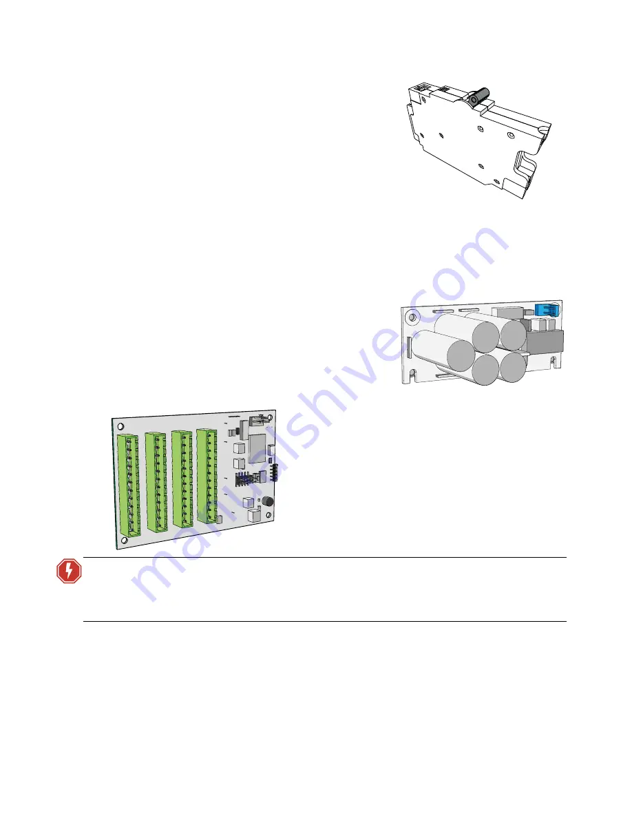
The Sensor IQ Breaker Panel ships standard with 12, 24, or 48
single-pole breakers included but not installed. Configured
racks with a combination of single-pole, double-pole, and
three-pole breakers are available as custom, or as a field-
installed panel option. Reference
and
Option Cards and Kits
Option cards are available for field installation into the Sensor
IQ Breaker Panel. Each option adds another level of features
and functions to the Sensor IQ Breaker Panel and the
installation.
For more information on the specification or installation of option cards, see the appropriate
installation guide supplied with the option card.
Ride-Thru Option
The Ride-Thru Option (IQ-RTO) maintains power to the
Sensor IQ Breaker Panel controller for a minimum of 15
seconds in the event of a brown-out or power loss.
• The ride-thru option card installs using stand-offs
to the inside wall of the low-voltage box.
0–10V Dimming Control
WARNING:
RISK OF DEATH OR INJURY BY ELECTRIC SHOCK! 0–10V wiring may not be
fully isolated from high voltage AC power. Do not assume that 0–10V wiring
is safe to touch, even when run as an NEC Class 2 signal. Test for AC voltage
to ground before terminating any 0–10V control wiring to the Sensor IQ.
J1 Flu
o
rescent 19-24
J
2
Flu
o
re
sc
e
nt
1
3
-18
J
3
Flu
o
re
scen
t
7
-1
2
J4
Fl
uo
res
c
e
n
t
1-
6
The 0–10V Dimming Control option card (IQ-LVD) provides 24
outputs for control of 4-wire current-sink, 0–10 VDC
fluorescent or electronic loads.
• Each of the 24 outputs are rated to control a maximum
of 400 mA per channel (up to 50 ballasts per channel).
• Loss of power at the Sensor IQ Breaker Panel controller
results in releasing control levels to full.
• The IQ-LVD option card installs using stand-offs to the
inside wall of the low-voltage box.


