ETC Setup Guide
ERn Ethernet Switch Module
ERn Ethernet Switch Module
Page 3 of 3
ETC
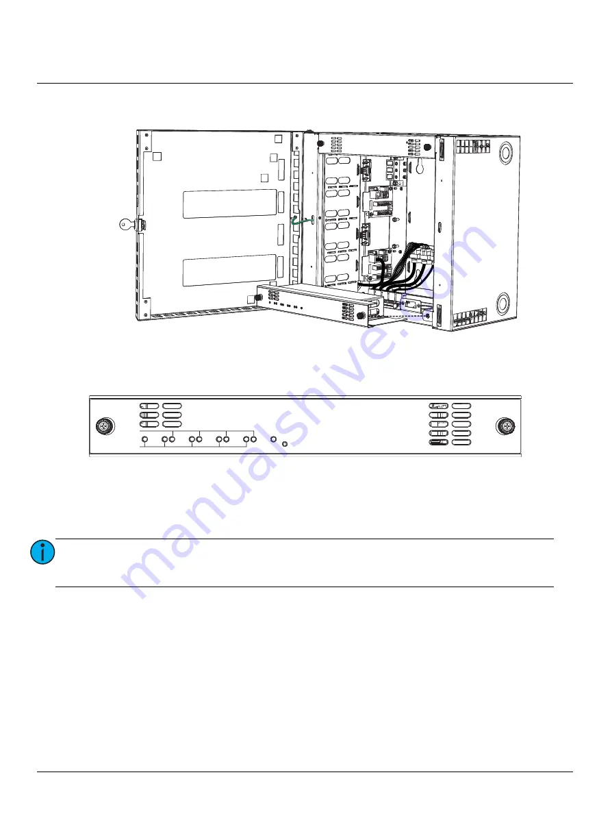
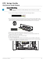
7: Install the Ethernet switch option module into the enclosure and secure it in place using the captured
screws provided.
Status Indicators
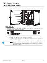
When power is applied to the ERn, the Paradigm Ethernet option module LEDs, located on the front panel,
indicate main power, data, and PoE power status.
• The power LED is blue and will illuminate when the Ethernet switch is powered.
• The LINK/ACT and PoE power LEDs are typical of an Ethernet switch.
- The Link/Act indicator is green and is on if there is a device connected to that port. A blinking LED
indicates data activity on the port.
- The PoE indicator is yellow and will be on if the Ethernet switch is supplying power to the device
connected to that port. A blinking PoE LED indicates a powering error on that port.
Note:
Port one does not have a PoE power indicator as it does not supply power. Port one is
always connected to the Paradigm architectural control processor which is powered by
the ERn rack power supply.
PoE
Power
LINK/ACT
1
2
3
4
5


