background image

ETC Installation Guide

SmartSwitch to Echo Relay Panel Feedthrough Retrofit Kit

SmartSwitch to Echo Relay Panel Feedthrough Retrofit Kit

Page 14 of 14

ETC

Power Up and Test

1. Return control power to the panel.

2. The Power Control Processor will turn on once power has been restored. Press the light bulb button 

to access the output check menu. 

3. Using the up and down arrows scroll through each relay, verifying they are each recognized by the 

panel. For additional information on menu setup, reference the 

Power Control Processor 

Configuration Manual

.

4. Power up the individual branch breakers and test for normal operation and control.

Additional manuals are available for reference at 

etcconnect.com

• See the 

ERP-FT Installation Manual

 for information on cable routing, power up, test, maintenance, and 

option card installation.

• See the 

Power Control Processor Configuration Manual 

for information on setting up and using the 

Power Control Processor. 

FCC Compliance

SmartSwitch to Unison Echo Retrofit Kit

(For any FCC matters):
Electronic Theatre Controls, Inc.
3031 Pleasant View Road
Middleton, WI 53562
+1 (608) 831-4116

etcconnect.com

This device complies with Part 15 of the FCC Rules. Operation is subject to the following two conditions: (1) 
This device may not cause harmful interference, and (2) this device must accept any interference received, 
including interference that may cause undesired operation.

Note:

This equipment has been tested and found to comply with the limits for a Class A digital 

device, pursuant to part 15 of the FCC Rules. These limits are designed to provide 

reasonable protection against harmful interference when the equipment is operated in a 

commercial environment. This equipment generates, uses, and can radiate radio frequency 

energy and, if not installed and used in accordance with the instruction manual, may cause 

harmful interference to radio communications. Any modifications or changes to this 

product not expressly approved by Electronic Theatre Controls, Inc. could void the user’s 

authority to operate the product. Operation of this equipment in a residential area is likely 

to cause harmful interference in which case the user will be required to correct the 

interference at his own expense.

Summary of Contents for ERP24-FT

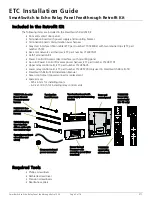
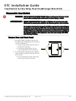
Page 1: ...nstallation of this retrofit kit into both the 24 and 48 position SmartSwitch Adding a retrofit kit to a SmartSwitch Relay Panel changes the panel model With the retrofit kit installed the panel becomes an Echo Relay Panel Feedthrough ERP24 FT or ERP48 FT WARNING RISK OF DEATH BY ELECTRIC SHOCK Failure to disconnect all power to the panel before working inside could result in serious injury or dea...

Page 2: ...y control card ETC part number 7123B5635 Lower relay control card ETC part number 7123B5735 only used in SmartSwitch 48 retrofit SmartSwitch Retrofit Kit Installation Manual Green control card power connector replacement Spare screws M5 x 6 mm for installing doors 6 32 x 1 4 inch for installing relay control cards Required Tools Phillips screwdriver Flatblade screwdriver Precision screwdrivers Nee...

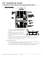
Page 3: ... bottom door panel and screws they will be reused WARNING RISK OF DEATH BY ELECTRIC SHOCK Failure to disconnect all power to the panel before working inside could result in serious injury or death AVERTISSEMENT RISQUE D ELECTROCUTION Travailler à l intérieur du panneau sans avoir déconnecté le courant peut entrainer des blessures graves voire mortelles De energize main feed to the panel and follow...

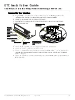
Page 4: ...ntly on the orange connector to disconnect the power input to the relay control card 6 Replace orange connectors with green connectors For 48 position panel only 1 Remove the RJ45 connections red and black control cables and orange header connection from the lower control card in the same manner as with the upper control card 2 Remove the two Phillips screws securing the RJ45 splitter board to the...

Page 5: ...maining wires 5 Remove the I O panel This panel is no longer needed and can be discarded 6 Remove any remaining adhesive back cable mounts 7 Remove the four 8 32 x 3 8 inch screws that secure the User Interface to the rear of the SmartSwitch enclosure Set the screws aside they will be reused to secure the new User Interface to the same location in the panel 8 Remove the User Interface from the Sma...

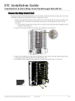
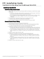
Page 6: ...connects each relay to the control card ETC recommends using needle nose pliers to avoid detaching the wires from the connector If a wire breaks replace the harness with one of the extra red and blue wire harnesses that are included in the retrofit kit 2 Repeat for each relay installed on both the upper and lower control boards 3 Remove the thirteen 6 32 screws securing the upper control card to t...

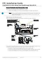
Page 7: ...g the flatblade screwdriver loosen the two screws on the control power termination block There are two blue wires and one white wire currently terminated at this block 3 Terminate the new blue wire in the same location as the existing blue wire If you are working with a 24 position panel there is one existing blue wire in the control power termination block Terminate the new blue wire in the same ...

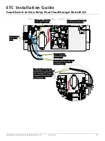
Page 8: ...to power supply Control power termination block Existing blue and white wires to lower termination block 48 circuit panel only Blue and white panel power wires are routed from the upper termination block behind the circuit board and down to the lower termination block 48 circuit panel only Existing blue and white wires to transformer Upper termination block and control card connections ...

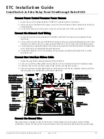
Page 9: ...ted in Connect Control Power Wiring on page 7 to the power supply located on the termination board 1 Loosen two of the termination screws located on the top of the power supply 2 Insert the fork terminal on the blue wire beneath one of the screws and tighten the screw securing the wire in place 3 Insert the fork terminal on the white wire beneath one of the screws and tighten the screw securing th...

Page 10: ... relay control card as shown above 1 Feed the second pair of wires through the access hole near the power supply 2 Guide the wires behind the circuit board and through the grommet to the lower relay control card 3 Press the white and black two pin connector into the header on the lower relay control card Note There is an additional length of red and black wire that is only used for a 48 position p...

Page 11: ...ct the network card to the building wiring using the provided patch cable from the Cat5 termination kit Connect User Interface Ribbon Cable 1 Locate the gray ribbon cable provided with the retrofit kit 2 Push one end of the ribbon cable into the header on the termination board until seated securely 3 Push the other end of the ribbon cable firmly into the user interface header 4 Clip one retaining ...

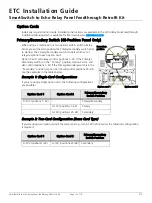
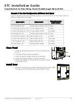
Page 12: ... 24 If the Primary Secondary switch is in the Primary position Option Card 2 will also control positions 1 24 If the Primary Secondary switch is in the Secondary position Option Card 2 will control positions 25 48 See the examples in the tables below Example 1 Single Card Configurations If you are using a single option card the following configurations are possible I Example 2 Two Card Configurati...

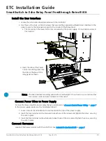
Page 13: ...e is ready to be closed 5 Fold the User Interface mounting panel up into place and secure with four M5 screws Install Door 1 Attach the new door panel provided with the Retrofit Kit using a Phillips screwdriver and the four previously removed M5 door screws Option Card 1 Option Card 2 Primary Secondary Switch Position 0 10V positions1 24 Contact Input positions 1 24 Primary Contact Input positions...

Page 14: ...y FCC matters Electronic Theatre Controls Inc 3031 Pleasant View Road Middleton WI 53562 1 608 831 4116 etcconnect com This device complies with Part 15 of the FCC Rules Operation is subject to the following two conditions 1 This device may not cause harmful interference and 2 this device must accept any interference received including interference that may cause undesired operation Note This equi...

Reviews: