ETC Installation Guide
SmartSwitch to Echo Relay Panel Feedthrough Retrofit Kit
SmartSwitch to Echo Relay Panel Feedthrough Retrofit Kit
Page 7 of 14
ETC
Install the Retrofit Kit
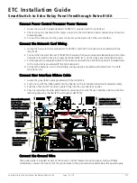
Install the Relay Control Cards
1. Install the new relay control cards using the same 6-32 screws that were removed from the original
control cards.
• The kit for the 24-position panel contains one card and uses 13 existing screws. The kit for the
48-position panel contains two cards and uses 26 existing screws.
• When upgrading a 48-position panel, identify the upper control card by the white part number
sticker with ETC part number 7123B5635. The lower control card is ETC part number
7123B5735.
2. Reconnect all blue and red relay harnesses that were previously disconnected.
• Match the relay number to the number on the control board.
3. Reconnect the power inputs to the relay control cards with the new green headers.
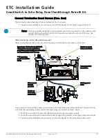
Connect Control Power Wiring
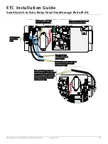
1. Locate the blue and white wires provided with the retrofit kit.
2. Using the flatblade screwdriver, loosen the two screws on the control power termination block.
• There are two blue wires and one white wire currently terminated at this block.
3. Terminate the new blue wire in the same location as the existing blue wire.
• If you are working with a 24-position panel, there is one existing blue wire in the control power
termination block. Terminate the new blue wire in the same location as the existing blue wire.
• If you are working with a 48-position panel, there are two existing blue wires in the control
power termination block. Terminate the new blue wire in the same location as the existing blue
wires.
4. Tighten the screw to secure the wires in place.
5. Terminate the new white wire in the same location as the existing white wire.
• If you are working with a 24-position panel, there is one existing white wire in the control
power termination block. Terminate the new white wire in the same location as the existing
white wire.
• If you are working with a 48-position panel, there are two existing blue wires in the control
power termination block. Terminate the new white wire in the same location as the existing
white wires.
6. Tighten the screw to secure the wires in place.


