ETC Installation Guide
SmartSwitch to Echo Relay Panel Feedthrough Retrofit Kit
SmartSwitch to Echo Relay Panel Feedthrough Retrofit Kit
Page 9 of 14
ETC
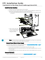
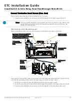
Install the User Interface
1. Locate the termination board provided with the retrofit kit.
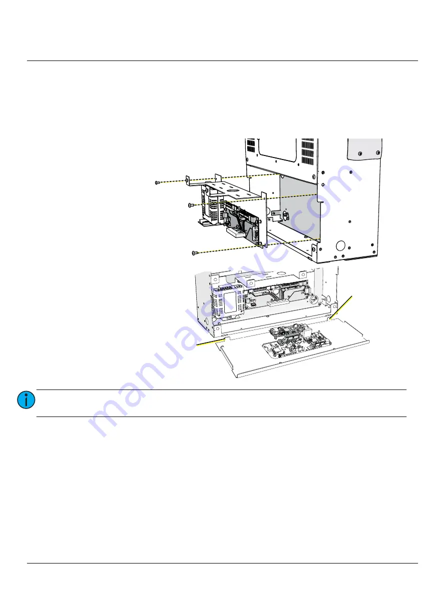
2. Use three of the 8-32 x 3/8 inch screws that secured the original SmartSwitch User Interface to the
panel to secure the termination board to the interior of the Relay Panel.
• The mounting in the lower left corner is covered by the power supply. Do not install a screw in
this location.
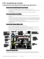
Connect Power Wires to Power Supply
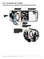
Connect the blue and white power wires that you terminated in
to the power supply located on the termination board.
1. Loosen two of the termination screws located on the top of the power supply.
2. Insert the fork terminal on the blue wire beneath one of the screws and tighten the screw, securing
the wire in place.
3. Insert the fork terminal on the white wire beneath one of the screws and tighten the screw, securing
the wire in place.
Connect Harnesses
Locate all harnesses included with the retrofit kit. See
.
Note:
The User Interface mounting panel will not hold weight. Do not lean on, or set items other
than option cards and wire harnesses on this panel.
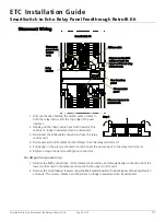
3. Insert the tabs of the Power
Control mounting panel into
the slots at the base of the
relay panel as shown.
Mounting
panel tab
Mounting
panel tab


