background image

Installation

16

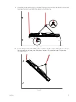
Figure 13: Backbone clamp on backbone stiffener

Summary of Contents for EVF-0509

Page 1: ...Part Number 8070M2000 Rev D Released 2019 05 Vortek NXT Hoist CE User Operations Manual ...

Page 2: ...with a new product or when servicing We have checked that the contents of this document correspond to the machinery described There may be discrepancies nevertheless and no guarantee can be given that they are completely identical The information contained in this document is reviewed regularly and any necessary changes will be included in the next edition To view a list of ETC trademarks and pate...

Page 3: ...ment 7 Chapter 5 Technical Description 8 5 1 Vortek NXT Specifications 8 Chapter 6 Incoming Goods Transport and Storage 9 6 1 Unloading Vortek Hoists 9 6 2 General Information for Storage 11 Chapter 7 Installation 12 7 1 General Information on Installation 12 7 1 1 Vortek NXT Hoist Installation Tool List 12 7 2 Uncrating Vortek Hoist 13 7 3 Basic Hoist Components 13 7 4 Attaching Backbone Stiffene...

Page 4: ...Box Address 31 8 3 Power On 32 8 3 1 QT1 C Field Service Kit Start Up 32 8 4 Testing and Resetting E stop System 33 8 5 Start Movement with QT1 C Field Service Kit 34 8 6 Stop Movement with QT1 C Field Service Kit 34 8 7 Hoist Commissioning Requirements 34 8 7 1 Set Upper and Lower Limits 34 8 8 Advanced Operations with QT1 C 38 8 8 1 Position Presets 38 8 8 2 Load Profiles and Monitoring 38 Chapt...

Page 5: ...al 51 Chapter 13 Technical Data 52 13 1 Vortek NXT Technical Data 52 13 1 1 Emission Sound Pressure Level 53 13 1 2 Product Dimensions Weight 53 13 1 3 Crated Dimensions Weight 53 13 1 4 Speed 54 13 1 5 Hoist Capacity 54 13 1 6 Fly Travel Distance 54 13 1 7 Number of Lift Lines 54 13 1 8 Braking 54 13 1 9 Limit Switches 54 13 1 10 Load Sensing 54 13 1 11 Mounting 54 Chapter 14 Spare Parts 55 Chapt...

Page 6: ...provided to allow use of the hoist without the presence of a primary control system Qualified Person Person who by possession of a recognized degree or certificate of professional standing or who by extensive knowledge training and experience has demonstrated the ability to solve problems relating to the subject matter and work Risk Combination of the probability of occurrence of harm and the seve...

Page 7: ...on the unit and in this manual Do not modify a Vortek hoist in any way unless expressly told to do so by the manufacturer Do not modify the values and adjustments of the safety components and functionality outside the limits provided in this manual or without the written authorization of the manufacturer Do not open a Vortek hoist or remove the outer casing if the system is connected to a power so...

Page 8: ...otor drives Only authorized personnel must carry out any installation commissioning or maintenance of the electrical systems All drive systems have been tuned at the factory and will not require any additional alteration or adjustment by the owner s personnel unless specifically authorized by an ETC representative WARNING Do not exceed point load Uniform Distributed Load UDL or Working Load Limit ...

Page 9: ...ot use a Vortek hoist without having performed the daily inspection See 11 1 General Checks on page 47 WARNING Do not connect the Vortek hoist electrical connection to any power supply socket that has not been tested by a qualified individual WARNING Do not connect a Vortek hoist to a power source other than specified on the unit and in this manual WARNING Do not modify a Vortek hoist in any way u...

Page 10: ...Working Load Limit for all line sets in your system NEVER exceed the working load limit or the Hoist Capacity for any line set WARNING Do not enable the hold to run control button up or down button in any other way than described in this manual The hold to run control button must always be under manual operator control WARNING Do not use a Vortek hoist if it does not appear to be in 100 perfect wo...

Page 11: ...s in your system number of motors external E stop stations etc Please email comments about this manual to TechComm etcconnect com Americas United Kingdom Electronic Theatre Controls Inc Electronic Theatre Controls Ltd Technical Services Department Technical Services Department 3031 Pleasant View Road 26 28 Victoria Industrial Estate Middleton WI 53562 Victoria Road 800 775 4382 USA toll free Londo...

Page 12: ... atmosphere and or in contact with dangerous substances This equipment is not intended to lift move fly suspend or automate people or domesticated animals and such use is strictly prohibited 4 2 Operating Environment The Vortek hoist is designed for indoor use only and designed to work in ambient temperatures between 0 C and 40 C 32 F and 104 F 10 90 non condensing humidity The Vortek hoist has an...

Page 13: ...d by Foundation QuickTouch or QuickTouch controls A Vortek NXT hoist is a fixed or variable speed electric wire rope winch designed for use in the entertainment and event industry Figure 1 Vortek NXT front view See 7 3 Basic Hoist Components on page 13 for more information Figure 2 System riser including the Vortek NXT with QT1 C Field Service Kit Note For physical dimensions of the controller see...

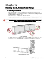
Page 14: ...ighs approximately 500 kg 1100 lbs There are only two places where the Vortek crates can be lifted with a forklift the side and the Motor End Figure 3 Lifting positions The first lifting point is from the Motor End Figure 4 with a forklift that has fork tines that are at least 104 cm 41 long a maximum of 22 cm 8 1 2 wide and 5 cm 2 thick to use this location Figure 4 Lifting by Motor End position ...

Page 15: ...Each Vortek crate Motor End will be labeled with the model number and or line set number Figure 6 Organizing the hoists as they are unloaded may help during installation Figure 6 Crate label Note When using this location spread the forks as wide as possible either side can be used to lift the crates CAUTION The Vortek hoists are not balanced at center so care must be taken when moving the units TA...

Page 16: ...d 60 C at 10 90 non condensing humidity If the hoist has been exposed to drastic temperature fluctuations i e during transport do not connect it to a power source immediately The change of temperatures can cause condensation to form on both exterior casings and interior parts which can damage the hoist if powered on Leave the Vortek hoist disconnected from a power source until it has equalized wit...

Page 17: ...cket 3 8 Drive 1 2 Socket 3 8 Drive 9 16 Deep Well Socket 1 2 Drive 3 4 Deep Well Socket 3 8 Drive Torque Wrench 3 8 Drive Ratchet 1 2 Drive Ratchet 18 Long 3 8 Drive Wobble Extension or Universal 1 4 Allen Wrench 3 32 Allen Wrench Cordless Drill with 3 8 Drive Attachment Tape Measure Metal Banding Cutter Nicopress Tool Cable Cutter Electrical Tape Utility Knife Laser Level Rubber Mallet WARNING U...

Page 18: ...f the bottom skid Figure 8 Lift crate top off bottom skid 3 Cut the banding and remove the poly sheeting from the hoist Figure 8 Two backbone stiffeners and the Vortek Hoist Installation Kit will be loosely attached on top of the unit Remove these items and place them in a safe location They will be required during this installation procedure 7 3 Basic Hoist Components Figure 9 Basic Hoist Compone...

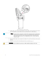
Page 19: ...he backbone 2 Repeat this process for the opposing side 3 Insert the threaded rod through the beam clamp while threading the nut onto the lead end Figure 12 4 Continue pushing the rod into the hole on the backbone stiffener and start threading the second nut onto the lead end the threaded rod will run into and through the second beam clamp Note If there is something that obstructs you from using b...

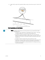
Page 20: ... the end of the second channel 7 Repeat for the other end of the stiffeners with the second clamp Figure 13 Note The beam clamps on the motor end of the hoist are installed in the very first position Depending on the installation environment the installation blocks and lifting clips may have to be used on the inside of the support I beams In this situation the backbone stiffeners will have to be i...

Page 21: ...Installation 16 Figure 13 Backbone clamp on backbone stiffener ...

Page 22: ...ior to being rotated into the proper lifting position and the clip when it has been locked into the channel Tighten the bolts on the lifting clips to 13 5 Nm 10 ft lb to secure the clips in place on the backbone Figure 14 Install hoist lifting clips WARNING Risk of personal injury and or damage to the hoist Do not lift the Vortek NXT hoist using methods other than the ETC s hoist lifting clips WAR...

Page 23: ... between the leading edge of the I beam and the Motor End beam clamp Figure 15 Positioning the hoist motor end Directly attach lift lines to the hoist lifting clip Figure 16 Each installation is unique Pre measure the wire rope to be sure to have enough to go the total distance of the lift WARNING The hoist weighs approximately 295 kg 650 lbs out of the crate Take precautions when lifting making s...

Page 24: ... Lift Hoist to I beams 1 With the hoist lifting clips securely in place on the hoist backbone lift the hoist out the skid approximately 7 6 cm 3 2 Check that all connections are secure at the hoist lifting clips CAUTION Make sure that the cables do not get caught on anything as the hoist is raised ...

Page 25: ...he I beams Figure 17 Figure 17 Positioning motor end beam clamps 4 Raise the hoist into position so the backbone is about 12 7 mm 1 2 below the I beams and start tightening the clamps using the 9 16 socket Figure 18 Only tighten until they contact the top of the lower flange of the I beam Figure 18 Attaching beam clamps to I beams 12 7 mm 1 2 in ...

Page 26: ...ment confirmed tighten the beam clamp bolts to a final torque of 23 27 Nm 17 20 ft lb by alternating between the two clamps until the hoist backbone is contacting the I beam adding support The threaded rod bends and applies constant pressure to the backbone stiffeners to minimalize vibration and noise Repeat for the Tail End set of beam clamps 9 Tighten all four 5 16 x 18 socket head screws on the...

Page 27: ...re rope are acceptable for use Loft blocks must have a minimum D d ratio of 25 1 D d ratio is the ratio between the diameter of the block and the diameter of the wire rope As this hoist uses 3 16 wire rope the minimum diameter of the pulley must be 120 mm 4 72 in Loft blocks and other routing devices must be rated for the load Loft blocks must be positioned so that the lift lines exiting the hoist...

Page 28: ...length Vortek hoists use 3 16 wire rope for all standard installations A 3 16 Nicopress aluminum sleeve with thimble is provided for use to terminate the cable end to the turn buckle or trim chain Only genuine Nicopress tools with the correct crimping inserts for the provided sleeves must be used Note Each Vortek NXT project has a detailed set of job drawings which determine the installation locat...

Page 29: ... The power supply to the Vortek hoist must be protected by an external fuse or circuit breaker with rating not exceeding 16A The wires in the supplied mains input connection cable are colour coded as follows Phase L1 Brown Phase L2 Black Phase L3 Grey or Black Neutral Blue Earth ground Yellow Green WARNING Confirm the number of crimps required for the Nicopress sleeve by reviewing the Nicopress cr...

Page 30: ...e 22 QT1 C Field Service Kit An international power supply kit has been provided for connection of the QT1 C Field Service Kit to a power source 1 Attach the international power supply cable to the regional specific power adapter 2 Attach the coaxial power connector to the receptacle on the QT1 C Field Service Kit Figure 23 Figure 23 QT1 C Field Service Kit connections E M ERGENCY STOP E M ERGENCY...

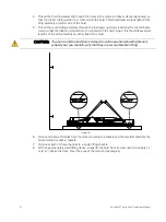
Page 31: ... sections detailed this method of mounting the hoist If you are planning to mount the hoist vertically the following procedure provides some guidelines for you to follow 1 Position the hoist in its crate adjacent to the lineset position where you will install the hoist 2 Remove the wooden cover banding and any packing material 3 Create two 4 5 m 15 ft sling assemblies using 3 16 diameter galvanize...

Page 32: ...act with the hoist Again this should leave equal lengths of the sling assembly on either side of the hoist Figure 26 6 Terminate the two thimbles from the motor end sling to a shackle and the two thimbles from the tail end sling to another shackle 7 Terminate both of these shackles to a single lifting shackle 8 With an appropriately sized lifting device slowly lift the hoist from its crate until i...

Page 33: ...n and terminate the end of a second lifting device to the lifting ring Figure 27 10 Incrementally raise the tail end lifting device while lowering the centered lifting device to change the orientation of the hoist from horizontal to vertical This should be done in a slow and controlled manner Figure 28 1 2 m 4 0 ...

Page 34: ... and backbone clamp as described in 7 4 Attaching Backbone Stiffeners on page 14 16 Continue tightening the motor end beam clamps until the backbone is tightly secured against the beam flange Torque to 23 27 Nm 17 20 ft lbs 17 Begin the same alternating sequence of tightening the tail end beam clamps until both sides are as close to contacting the mounting beam flange as possible 18 Install the ot...

Page 35: ...tions Make sure nobody is standing underneath the batten Call out the intended movement While Moving a Hoist Keep your eyes on the entire batten and the intended travel Never look at the controller display and never get distracted Stop the hoist if there is a problem Stop the hoist if you get distracted 8 1 Check Main Input Connections 1 Check that the 5 pin 16A CEE FORM Red plug from the motor co...

Page 36: ...Motor Control Box secured access panel 2 Confirm address dials are set to address 0 0 1 Figure 32 Figure 32 Motor Control Box address dials and limits 3 Replace the secured access panel WARNING RISK OF DEATH OR SEVERE INJURY DO NOT interfere or use the hoist limit switches or limit switch override buttons located near the three address switches These switches are for use by ETC trained authorized ...

Page 37: ...p This screen displays contact information for the installer responsible for the system or ETC s website and phone number Your installer may have chosen to display their contact information The software version is also displayed during the start up By default this contact information is displayed for 3 seconds To prolong the display of contact information indefinitely on a multi hoist controller p...

Page 38: ... prohibited as long as the stop button remains in the locked position Reset the E stop circuit by turning the red Emergency Stop button clockwise until it pops back into its raised position Figure 34 Figure 34 QT1 C Field Service Kit E stop After resetting the E stop you must also cycle power at the QT1 C Field Service Kit using the power keyswitch Note You will not be able to move the hoist until...

Page 39: ...te and you have verified the proper movement of the hoist This is done using the limit switch adjustment screws and override buttons at the rear of the hoist WARNING Do not move load into people or other obstacles such as scenery Machinery must only be operated from a line of sight position The entire load must be visible by the operator at all times during travel Note The up and down buttons are ...

Page 40: ...be set at roughly 15 cm below the lower limit Regardless of where you set the upper and lower limits the overtravel limits will be approximately 15 cm 6 in beyond these limits Figure 36 Limits diagram Vortek Hoist Loftblock 15 cm minimum Load attachment point 15 cm set at factory 76 mm between hard and soft limits 15 cm minimum to nearest point of conflict 76 mm between hard and soft limits 15 cm ...

Page 41: ... test the upper overtravel limit press and hold the UPPER OVERRIDE button on the Motor Control Box At the same time press the blue up button on the QT1 C until the hoist has travelled through the upper limit and is stopped at the upper overtravel limit 8 Press and hold the OVERTRAVEL OVERRIDE button on the Motor Control Box and then press the green down button on the QT1 C until the hoist has trav...

Page 42: ...n down button on the QT1 C until the hoist has travelled through the lower limit and is stopped at the lower overtravel limit 8 Press and hold the OVERTRAVEL OVERRIDE button on the Motor Control Box and then press the blue up button on the QT1 C until the hoist has travelled back up past the lower limit and into the normal operation range The remainder of system commissioning can only be done afte...

Page 43: ...ing lifted If the load is out of the allowable range movement is stopped and an error message is displayed on the LCD See Faults Causes and Remedies on page 44 In order to monitor the load a load profile must be learned by the hoist this is done by loading the hoist with the desired load and then allowing the hoist to learn that load Only one hoist can learn a load at any given time There are two ...

Page 44: ...8 Once the original limit is reached release the button Recording is complete 9 Turn the keyswitch back to RUN 10 Remove the key from the keyswitch or connect the QT1 C Field Service Kit to the next hoist and repeat the Quick Learn process Enabling Load Monitoring Load monitoring can be enabled or disabled for each hoist individually 1 Insert a key into the LOAD PROFILE keyswitch 2 Turn the keyswi...

Page 45: ...g is enabled and the load is lighter than the recorded load profile downward movement of the hoist will be disabled and an error message displays on the QT1 C Field Service Kit stating Load Too Light Upward movement is still permitted Regardless of whether load profiling is enabled or not the system always monitors the maximum hoist capacity at all times If the maximum hoist capacity is exceeded u...

Page 46: ... by the operator at all times during travel CAUTION To be operated by ETC trained authorized personnel only Once unplugged the E stop button on the remote will be inactive For this reason the remote control must be stored in an inaccessible space not visible to people when not connected to the system This will avoid the presence of an inoperable E stop button in case of an emergency Be aware of th...

Page 47: ...ion become inactive while the button is pressed The reverse is true as well If a preset has been programmed for the selected hoist the hoist will stop when it reaches the preset location To continue movement past this position release the up or down button and then press and hold again Travel will continue Up Stop To move the load in an upward direction press and hold the blue button depicting the...

Page 48: ...e pressed position once it is pressed Hoist travel will be prohibited as long as the Emergency Stop button remains in the locked position To unlock the stop button rotate the red Emergency Stop button clockwise until it pops back into its raised position Once the button is released you must return to the control station to cycle power by turning the POWER keyswitch to OFF and then back to ON This ...

Page 49: ...e plug Wrong or damaged CEE FORM receptacle No power to hoist Main power is not on Hoist motor control box CEE FORM connector is plugged into wrong receptacle Incorrect motor control box wiring Incorrect wiring of CEE FORM cable plug no contact between wire and pins Incorrect wiring of CEE FORM receptacle no contact between wire and pins Incorrect wiring or defective wiring of motor control box po...

Page 50: ...Local Verify that the area is safe Release the control station E stop button Local Down Stuck Cycle power with no buttons pressed If error recurs contact your system installer or ETC Technical Services Local Up Stuck Cycle power with no buttons pressed If error recurs contact your system installer or ETC Technical Services Low Trim The user defined lower limit has been reached Move the hoist in th...

Page 51: ...plete contact your system installer or ETC Technical Services Slack Cable Check to see that batten is not resting on something and that all lift lines are taut Slack Limit Release Move button and verify proper cable travel Ensure no slack cables remain Try Move button again Soft Lower Limit The commissioning lower limit has been reached Move the hoist in the up direction Soft Upper Limit The commi...

Page 52: ...ement with QT1 C Field Service Kit on page 34 4 While operating the hoist pay close attention to any unusual operating noises 5 While operating the hoist press the E stop button Hoist operation must stop immediately See 8 4 Testing and Resetting E stop System on page 33 6 With the hoist in the lowered position inspect all batten terminations for wear and damage Note Records of Standard Inspection ...

Page 53: ... lubrication of the Acme screw Inspection of cable out sleeves and diverters Inspection of loft blocks see manufacturers recommendation for loft block service Inspection of hoist mounting hardware to the structural steel Inspection of mounting hardware of the loft blocks Inspection of the hoist backbone stiffeners Proper operation of the load brake Proper operation of the motor brake Inspection of...

Page 54: ...rating conditions Inspect the brake Measure the brake disc thickness Brake disc lining Measure and set working air gap Pressure plate Driver gearing Pressure rings Vacuum up the abraded matter Inspect the switch contacts and change if necessary e g in case of burn out Mechanical brake Every 400 operating hours Inspect the brake Check for signs of wear and or fatigue Look for buildup of dust around...

Page 55: ... must be tested independently during annual inspections WARNING While performing general checks annual inspection and maintenance including E stop testing make certain the entire location beneath the batten is closed off and all persons including the operator are away from the load ...

Page 56: ...uch as The Waste Electric and Electronic Equipment WEEE Regulations if necessary a specialist is to be commissioned Care must be taken that parts soiled with Acme screw leadscrew lubricant are disposed of separately according to the locally valid pollution control regulations Motor gearbox lubricant must be disposed according to the locally valid pollution control regulations Dispose of the motors...

Page 57: ...ide brake is post gearbox coupled directly to the drum both brakes are rated at 150 of static hoist capacity Hoists can be operated using QT1 C Field Service Kit QuickTouch or Foundation controllers All powerheads include overload protection and load profiling via built in load cells Four hard struck limit switches with LED indicator lights for more efficient installation Incremental encoder for a...

Page 58: ...Weight Not including backbone stiffener Model Travel Distance Wire Rope Size No of Lift Lines Hoist Capacity Speed EVF 0509 18 m 59 ft 4 76 mm 4 7 500 kg 1 102 lbs 0 90 cm s 0 35 in s EVF 0901 18 m 59 ft 4 76 mm 5 7 900 kg 1 984 lbs 10 cm s 4 in s Model Weight Range kg lb depending on lift lines Length cm in Width cm in Height cm in EVF 0509 284 323 626 712 391 153 9 32 12 5 51 20 EVF 0901 270 309...

Page 59: ...ry brake is a fully mechanical Weston style load side brake coupled directly to the drum rated at a minimum of 150 of full load 13 1 9 Limit Switches Direct struck style one up and one down limit switches function as the second end of travel limit Ultimate over travel circuit for maximum up and down end of travel disconnects power feeding the motor brake assembly 13 1 10 Load Sensing A pair of ele...

Page 60: ...or Footer Chapter 14 Spare Parts Spare parts are not available for individual sales and can only be installed by a qualified ETC Rigging Installer Contact ETC or a qualified ETC Rigging Installer to obtain spare parts ...

Page 61: ... 68 EC Applied Harmonised Standards in particular EN ISO 12100 2010 Safety of machinery General principles for design Risk assessment and risk reduction EN 60204 1 2009 Safety of machinery Electrical equipment of machines General requirements EN 60204 32 2008 Safety of machinery Electrical equipment of machines Requirements for hoisting machines EN 61800 5 2 2007 Adjustable speed electrical power ...

Page 62: ......

Page 63: ......

Page 64: ... 852 2799 1220 Paris FR 33 1 4243 3535 Web etcconnect com Support support etcconnect com Contact etcconnect com contactETC 2019 Electronic Theatre Controls Inc Trademark and patent info etcconnect com ip Product information and specifications subject to change ETC intends this document to be provided in its entirety 8070M2000 Rev D Released 2019 05 ...

Reviews: