background image

6  • Source Four MultiPAR

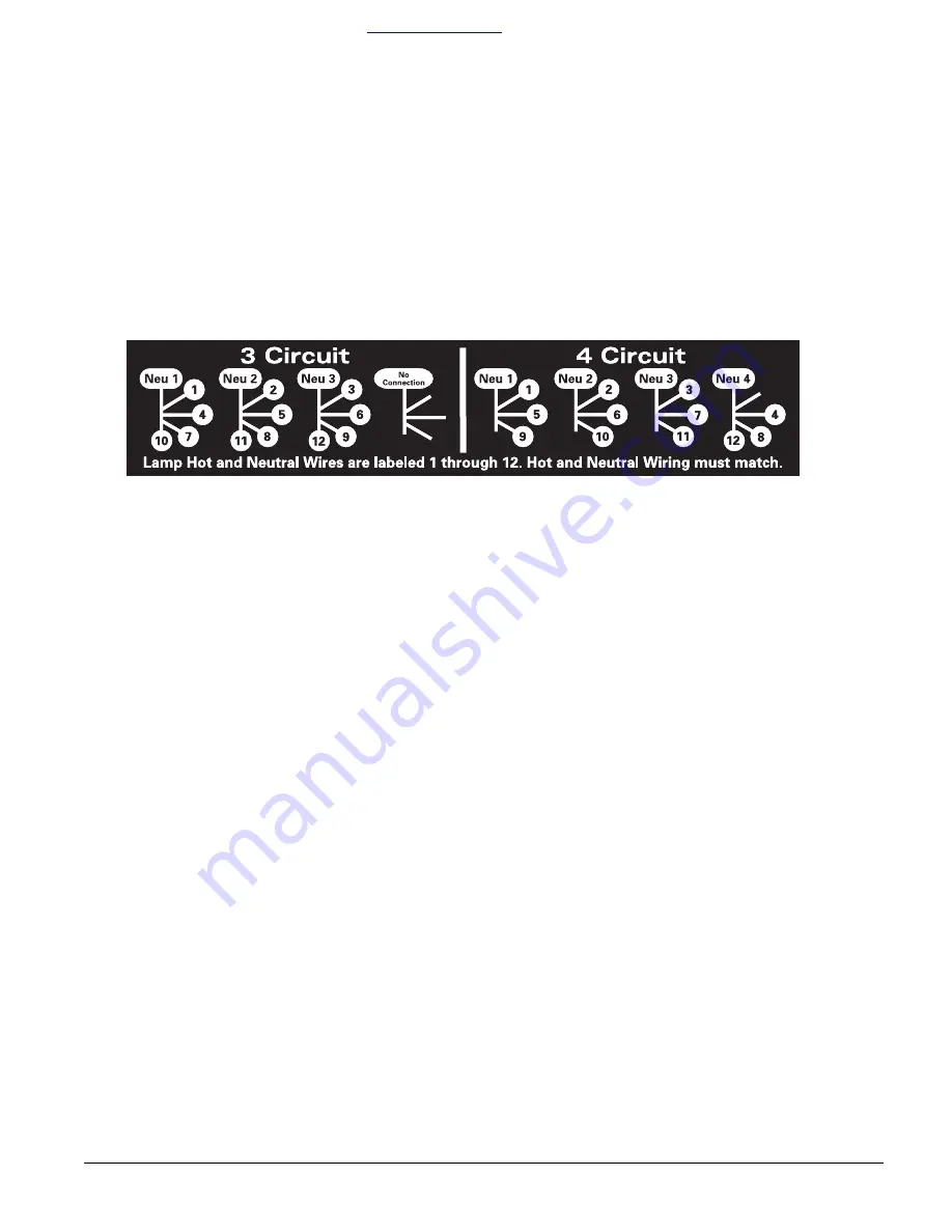
Circuit wiring configurations for the MultiPar-12.

The Source 4 MultiPAR can be wired for 3 circuit or 4 circuit configurations. Before changing the configuration, make 
sure that you have sufficient power (dimmer capacity) to operate the fixture. There are four terminal blocks inside the 
unit to place wiring. Each terminal block has four lead connection points. All of the hot and neutrals are labeled with 
a number for your convenience.

Three circuit configuration

1.

Disconnect power before changing the wiring.

2.

Loosen the captured screw on the back of the raceway and open the raceway lid.

3.

In the first terminal block on the left, insert the wires labeled 1,4,7,10. 

4.

In the second terminal block from the left, insert the wires labeled 2,5,8,11.

5.

In the third terminal block from the left, insert the wires labeled 3,6,9,12

6.

The fourth terminal block from the left is not used and is left empty.See 

Figure 7

 for detail.

Figure 7

Four circuit configuration

1.

Disconnect power before changing the wiring.

2.

Loosen the captured screw on the back of the raceway and open the raceway lid.

3.

In the first terminal block on the left, insert the wires labeled 1,5,9

4.

In the second terminal block from the left, insert the wires labeled 2,6,10.

5.

In the third terminal block from the left, insert the wires labeled 3,7,11.

6.

In the fourth terminal block from the left, insert the wires labeled 4,8,12. Se

Figure 7

 for detail.

ORDER DIRECTLY TODAY AT: 

www.BulbAmerica.com

 or CALL TOLL FREE 888-505-2111 

Summary of Contents for Source Four MultiPAR

Page 1: ...e provided with each MultiPAR Be certain to secure the MultiPAR to the batten by threading the safety cable through the end cap holes when hanging the unit Power requirements The Source 4 MultiPAR has several different standard as well as custom configura tions of electrical circuitry Make certain you are familiar with the wiring of the Multi PAR and that you have sufficient power dimmer capacity ...

Page 2: ...e operation 6 Insert lamp base into pin holes in socket assembly 7 Push down on the lamp base until the lamp is firmly inserted Make sure that the lamp is fully seated with the bottom of the lamp heat sink flush to the socket assembly surface 8 To reinstall the socket assembly insert until the heat sink base rests flush against the reflector then tighten the knurled bolt to secure the socket assem...

Page 3: ...300 hour HPL 575 120X 575 120 3 050ºK 2 000 hour HPL 575 230 575 230 3 200ºK 400 hour HPL 575 230X 575 230 3 050ºK 1500 hours HPL 575 240 575 240 3 200ºK 400 hour HPL 575 240X 575 240 3 050ºK 1500 hours HPL 750 115 750 115 3 250ºK 300 hours HPL 750 115X 750 115 3 050ºK 1000 hours HPL 750 120 750 120 3 050ºK 2 000 hour HPL 750 120X 750 120 3 050ºK 2 000 hour HPL 750 230 750 230 3 200ºK 300 hours HP...

Page 4: ...the unit the lens side facing you and tilted up slightly Figure 3 2 Hold the lens by the edge and position it so the convex side faces the back of the fixture Figure 4 Note Installing the lens with the convex side out will not impair the optics but it will make removing the lens more difficult 3 From the top of the fixture slide the lens behind one of the lens clips and into the cast metal lens ch...

Page 5: ...to step 5 5 Dampen a clean soft lint free cotton cloth with a mild soapy water solution and gently wipe the reflector 6 Remove any soapy water residue with a clean soft lint free cotton cloth dampened with water 7 Reinstall a lens before using the fixture CAUTION Do not use glass or window cleaners on the reflector Chemicals in the cleaners will harm the reflective coating Do not use paper towels ...

Page 6: ... insert the wires labeled 1 4 7 10 4 In the second terminal block from the left insert the wires labeled 2 5 8 11 5 In the third terminal block from the left insert the wires labeled 3 6 9 12 6 The fourth terminal block from the left is not used and is left empty See Figure 7 for detail Figure 7 Four circuit configuration 1 Disconnect power before changing the wiring 2 Loosen the captured screw on...

Page 7: ...mbly 16 AWG Wire Silver Contact 3 5 or 7ft long 2 2 W330 02 TP22 CLCM assembly ceramic 1 3 W330 03 TP22 CLCM assembly mica 1 1 6 7061A2027 Lamp Burner Assembly 3ft 1 1 6 7061A2028 Lamp Burner Assembly 5ft 1 1 6 7061A2029 Lamp Burner Assembly 7ft 1 6 7061A3061 Thumbscrew 1 7 various HPL lamp 1 ORDER DIRECTLY TODAY AT www BulbAmerica com or CALL TOLL FREE 888 505 2111 ...

Page 8: ...K mail etceurope com Asia mail etcasia com Service service etcconnect com Toll free 800 775 4382 Comments about this document techcomm etcconnect com Copyright 2002 Electronic Theatre Controls Inc All Rights Reserved Product information and specifications subject to change 7061M1014 Rev B Released 2 03 Spare parts list Source Four MultiPAR Final Assembly Reference Number Part Number Description Qu...

Reviews: