409-35011
Rev D
37
of 83
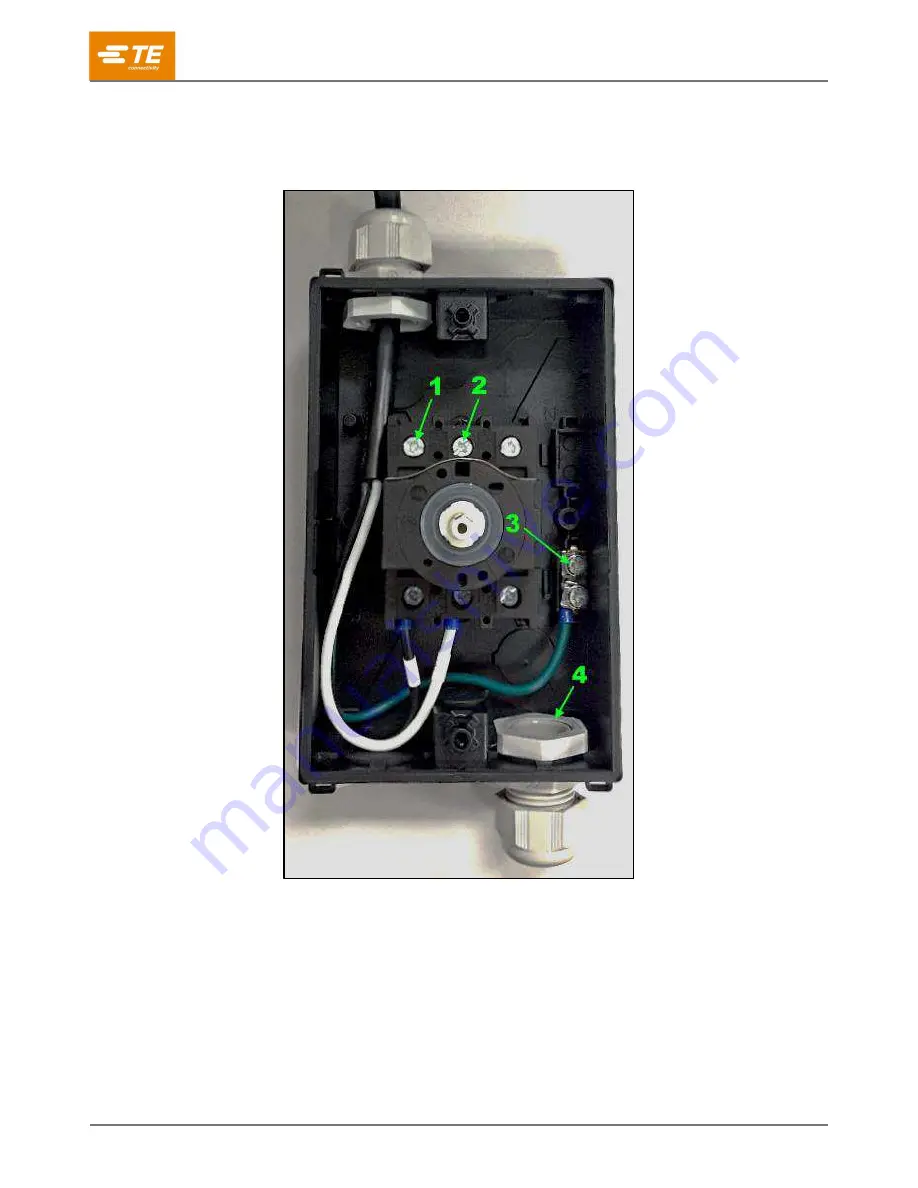
7. Feed the power cord through the cable gland at the bottom of the disconnect enclosure (Figure 44).
8. Connect line conductors to main disconnect switch terminals (Figure 44).
Figure 44: Interior of disconnect enclosure
1
L1
2
N or L2
3
Ground
4
Power cord cable gland


